David Avercrombie of Mentor won the award for the best tutorial at the 2012 TSMC OIP for his presentation, along with Peter Hsu of TSMC, on Finding and Fixing Double Patterning Errors in 20nm. The whole presentation along with the slides is now available online here. The first part of the presentation is an introduction to double patterning but I’m going to assume everyone already has that background information. If not, look at my earlier blog here.
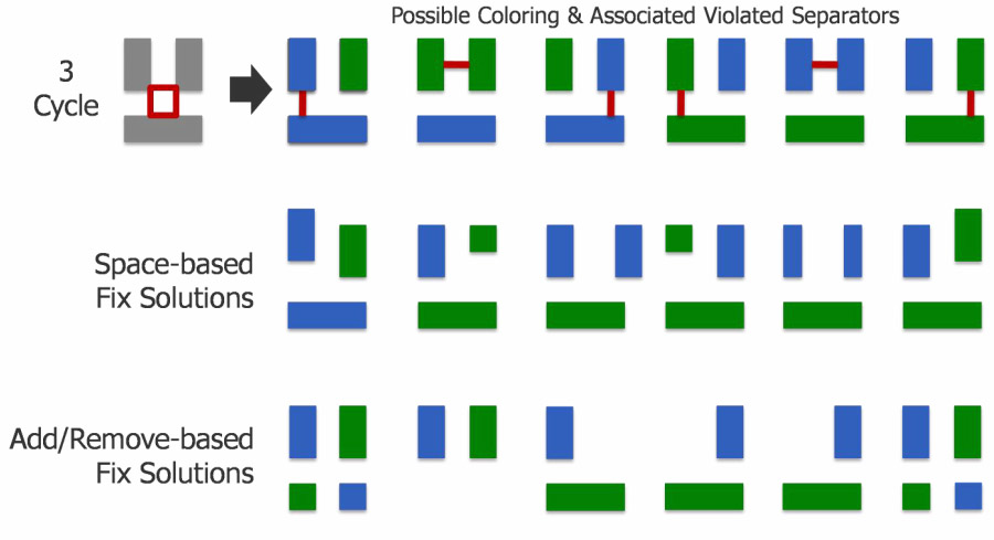
The most common double patterning error is what is called an odd-cycle path. This is when an odd number of polygons are arranged so that there are minimum spacing (or technically spacing that are close enough to require the polygons to be on separate colored masks) between them in a loop. The simplest case is shown above where there are three polygons, and each has to be a different color from the other two, which is obviously impossible with only two colors to go around. It is worth emphasizing that there isn’t just a single spacing that is in violation, or a particular coloring that is in violation. It is impossible to correctly color the polygons. Instead of giving a spurious coloring and highlighting one of the violations as being “the” error, the violation is indicated by a square (or more complex polygon for more complex violations) that shows which are the polygons in the cycle (as in the above picture). The violation can be fixed by either increasing a spacing so as to break the cycle, or by removing a polygon completely, either breaking the cycle or making the cycle even (which is not a problem since it can be colored).
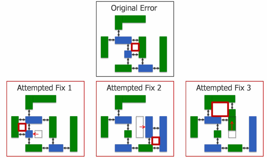
One problem is that moving a polygon to fix one odd cycle can often cause the whack-a-mole effect whereby a new odd cycle gets created as in the above examples. This can obviously be frustrating, to say the least.
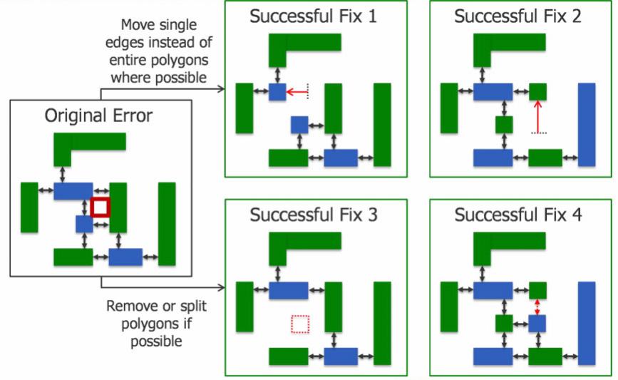
David’s rules of thumb for not getting into endless odd-cycle purgatory is:
- Move single edges as opposed to entire polygons when possible. This minimizes the chance of introducing unexpected new errors.
- Remove (or split) polygons. Again, this is less likely to produce new errors.
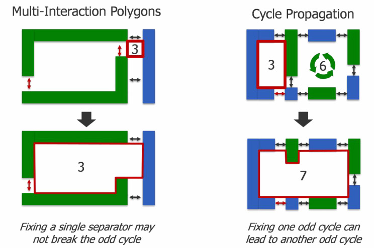
The rules are not foolproof however. One complication is that fixing one odd cycle path might have the effect of changing a nearby even cycle path (and therefore not a problem) into an odd cycle path and so creating a new violation, as in the two examples above. Mentor’s Calibre has some (apparently patented) technology for highlighting warnings to show where nearby paths intersect with error paths and so, at the very least, care must be taken. Watch the webinar for details.
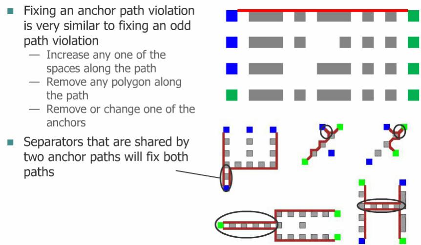
One final problem occurs with anchor paths, also known as pre-coloring. It is possible for the designer to select explicitly which of the two masks certain polygons must appear on. For example, the power and ground nets might be selected as going on the same mask to ensure that variation between the two nets is minimized. Of course, give a designer manual control and there is plenty of scope to get it wrong and create odd cycle paths between similarly colored polygons (or even cycle paths between different colored polygons) both of which make the design uncolorable. The fixes are mostly similar to any other odd cycle path, although there is another potential option which is to reduce the amount of pre-coloring or change the pre-coloring to colorable overall.
Of course real layout may have both odd path violations and anchor path violations all mixed up together in the same part of the design. David’s advice is to attack the odd cycle path violations first since that often fixes some of the anchor path violations in any case. Then worry about anchor path violations.
View the webinar here.
Share this post via:


Comments
0 Replies to “Fixing Double-patterning Errors at 20nm”
You must register or log in to view/post comments.