webinar banner AI 2026 v2

A True Signoff for 7nm and Beyond

A True Signoff for 7nm and Beyond
by Alex Tan on 08-13-2018 at 12:00 pm

The Tale of Three Metrics
Meeting PPA (Performance, Power and Area) target is key to a successful design tapeout. These mainstream QoR (Quality of Results) metrics are rather empirical yet inter-correlated and have been expanded to be linked with other metrics such as yield, cost and reliability. While the recent CPU performance race is less intense as Moore’s Law based scaling is increasingly costlier and more complex, power is taking the center stage. This has been intensified by the proliferation of more silicon geared toward addressing mobility (automotive, wireless-augmented- anything), distributed applications (Internet-of-Things) or scalable computing (multi-core).

Many of the adopted low-power implementation flows have shown that a holistic approach is necessary in order to achieve an optimal power target. It must also be initiated early at the architectural level such as addressing multiple power domains and clock domain partitioning, followed by power optimization at different level of the implementation stages. Concurrently, an accurate power analysis is required to provide feedback for needed adjustments to the optimization constraints as tradeoff recurrences are expected among these metrics.

Power Signoff Challenges
Power signoff checks power integrity of the grid. According to Jerry Zhao, Cadence Product Director, today designs can be categorized into two types for the purpose of analyzing the power grid constructions and identifying its challenges. The first design type demands capacity as it contains billions of instances and nodes such as the power-hungry oriented GPUs (Graphical Processing Unit) or CPUs for machine learning. The other is small in size but more sophisticated, which requires multiple power domains (such as IoT related chips) or special needs (such as packaging integrated analysis for automotive) –for this type, a higher analysis accuracy is needed.

Additionally, with the advanced nodes such as 7nm and 5nm FinFETs where metal resistance is more pervasive, higher correlation accuracy is also required between the implementation estimates and the analysis results generated by the signoff tools. In flow utilizing a traditional signoff approach, non-converging iterations are common occurrences as it relies on the use of design margins as well as due to a disconnect in either the underlying data model or the optimization/analysis engine of the associated point tools.

Cadence True Signoff Solution
As part of a tapeout signoff, design teams perform various validation including physically related verification (DRC, LVS, reliability), timing and power. While it is common to have crosstalk and SI (Signal Integrity) effects concurrently done with timing analysis, power verification (related to IR drop, electromigration/EM) is traditionally decoupled from timing analysis, in spite of the fact that an IR induced lower power biasing and the remedy to an EM avoidance may incur significant timing differentials that could change the criticality of a timing path.

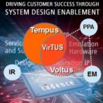
Driven by such tighter correlation needs especially in the advanced nodes domain, Cadence launched project Virtus (Voltus IR drop TempUS technology) which integrates the power and timing analysis to yield a true signoff solution. It had also been aligned with the existing Cadence digital implementation flow for both QoR predictability and convergence. The overall solution is dubbed full-flow digital.

As discussed during Cooley’s DAC 2018 Troublemaker Panel, Jerry shared a customer case involving a high frequency design. The 3Ghz design passed signoff using other third party power and timing tools, but failed to perform on silicon at the targeted frequency by several hundreds of Mhz. This design was then subjected to true signoff analysis, which was able to uncover the presence of IR drop violations that could induce timing violations comparable to the earlier post-silicon observation.

How much impact does an IR drop violation have on timing? At the DAC theater presentation, Cadence showcased such IR induced timing violations on a 2.5Ghz, 7nm CPU based design testcase. A non-critical path having +31ps slack and passing power integrity analysis with +42mV margin, was identified with true signoff as failing timing by -33ps due to the presence of proximity aggressors (equivalent to a 8% slow down in speed). This path interestingly was not one of the top-paths, instead, it was buried in the deeper non-critical path bin.


Speed and Parallelism

Since scalability and performance are needed for power integrity analysis, Cadence has recently rolled-out Voltus-XP, enhanced with extensive parallelism algorithm to support power grid signoff on giga-scale designs with massively distributed processing. It is cloud ready and provides up to 5x speedup.

Full-Flow Digital Solution
The tight handshake exemplified between Voltus and Tempus seems to be just one of the many close interactions among Cadence tools as shown in Full-Flow Digital Solution diagram, which is inline with this year Cadence’s slogan of being a system design enabler.

“Design closure is tightly correlated with how a cell is placed and routed as it impacts how current flows through the placed region and thus, influencing the IR drop,” stated Jerry referring to Voltus-Innovus IR-drop-aware placement fixing.

As one move towards the top of the die, packaging has its own IR drop requirements that are different than chip level. It is more thermal centric and involves gradual change compared with quick voltage ramp. A similar handshake with packaging analysis is also needed. Designer is expected to iterate through the tools in the ecosystem though not required to be concurrent, in order to ensure a QoR convergence.

In addition to IR drop check, for 7nm and 5nm power integrity, meeting foundry driven EM rules requires a year-round team collaboration which culminates in passing foundry certification process.

Signoff Solution for The Advanced Nodes
Asked on his take with the adequacy of Cadence current tool offerings for 7nm or 5nm signoff, Jerry stated that implementation step could further leverage the analysis outcome. “When Voltus is running it will report hot-spot areas (i.e. with IR drop error) understood by Innovus and used to do IR aware placement fixing,” stated Jerry. The tool is smart enough to move the aggressor by a few rows based on a cost function. A rerun of Voltus is needed to ensure it is fixed. Using such approach designer can reduce the IR drop by 30% in one iteration. With multiple iterations, it would resolve significant number of IR related issues although it may not fix the whole problems as there are some designer imposed constraints such as not allowing tool to touch the clock trees.

Addressing it from another angle has been demonstrated through the use of Tempus timing signoff tool. Jerry said that as Voltus and Innovus shared the same database (data model), an integrated Tempus-Voltus timing analysis can be done and an ECO based on voltage report can be generated to fix timing violations.

To recap, both timing and power signoffs have become increasingly longer with more complex designs and advanced nodes. Cadence integrated signoff solution not only provides multi-dimensional analysis but also a tightly coupled solution with the optimization based tools to alleviate signoff bottlenecks.

For more info on Voltus please check HEREand Cadence silicon signoff HERE

SEMICON West – Leading Edge Lithography and EUV

SEMICON West – Leading Edge Lithography and EUV
by Scotten Jones on 08-13-2018 at 7:00 am

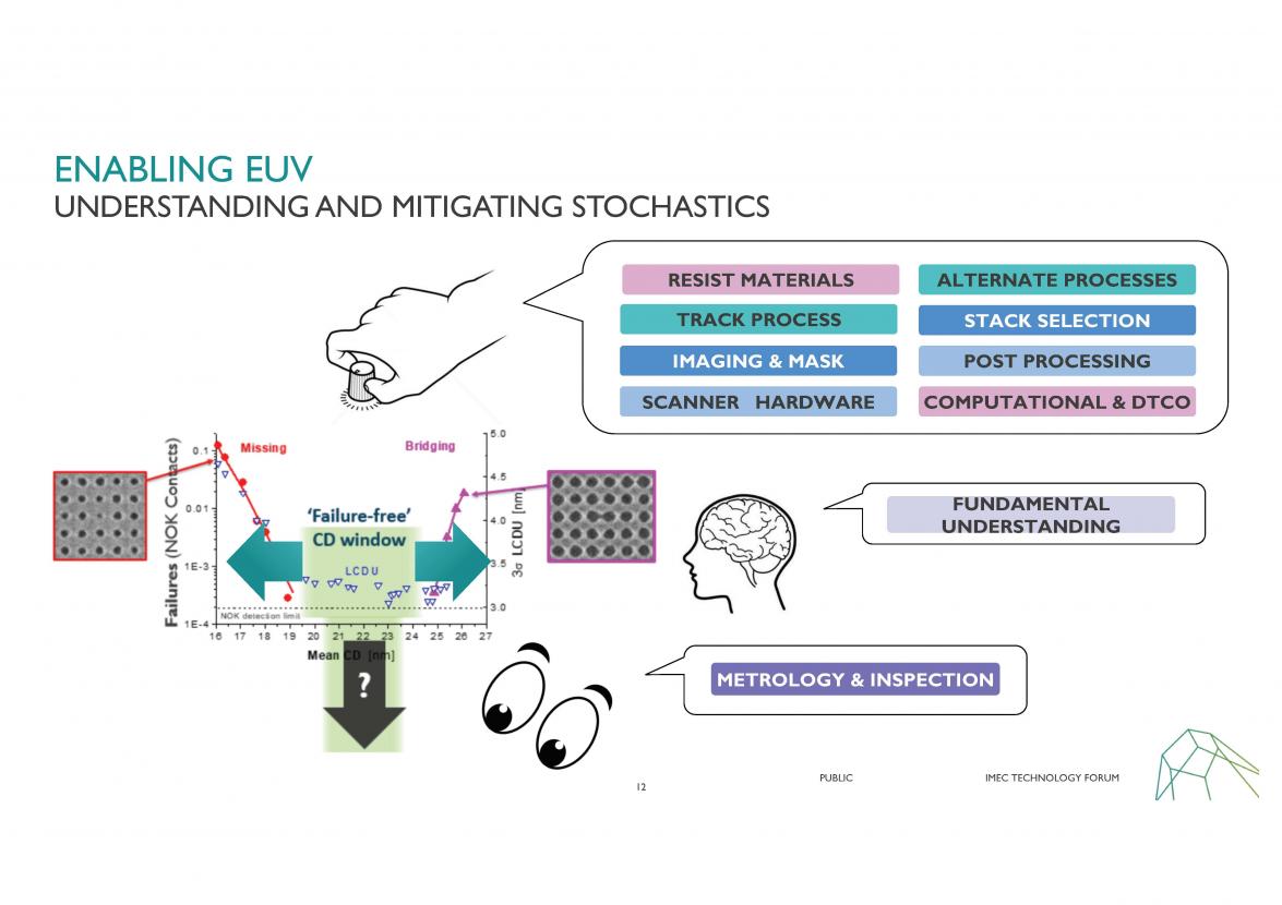
At SEMICON West I attended the imec technology forum, multiple Tech Spot presentations and conducted a number of interviews relevant to advanced lithography and EUV. In this article I will summarize what I learned plus make some comments on the outlook for EUV.
Continue reading “SEMICON West – Leading Edge Lithography and EUV”


Are We Over Uber? Bring on the Bots

Are We Over Uber? Bring on the Bots
by Roger C. Lanctot on 08-12-2018 at 12:00 pm

From sexual harassment, to surveilling regulators, to Uber drivers and taxi drivers committing suicide (because they can’t make a living) the pervasive creepiness of Uber continues to spread while the means of corraling this societal phenomenon creeps steadily forward like sclerotic mid-town traffic. The latest chapter in the Uber saga is unfolding in New York where court rulings (in line with similar rulings in California) may force gig drivers to be treated as employees just as the New York City Council is considering freezing for-hire licenses to combat negative urban traffic consequences.

Multiple studies show the onset of ride hailing apps such as Uber, Lyft, Via, Yandex, Grab and others around the world are driving up urban traffic congestion and undermining public transportation. The latest moves in New York, however, highlight the favor felt by under-served minority communities when it comes to fulfilling their ad hoc local transportation needs. In New York, and elsewhere, traditional Yellow Cabs have a reputation of insufficiently servicing minority riders (i.e. not stopping to pick them up) and their communities (i.e. refusing to drive to particular neighborhoods).

In New York, civil rights organizations and leaders including the New York Urban League and the Reverend Al Sharpton’s National Action Network have come out in opposition to the freeze on for-hire licenses and in support of Uber. These two currents perfectly capture the conundrum of a service that undercompensates drivers, many of whom are immigrants from minority communities, while providing superior service to those same minority and immigrant communities.

Let’s not get carried away, though, because Uber (and Lyft etc.) drivers are also well known for choosing not to accept certain fares (even though they may suffer app-based consequences). It’s not a perfect solution.

The New York Times chimed in with its own editorial solution of a minimum wage for gig economy drivers and a hike in taxi fares along with congestion charging for drivers of privately owned vehicles entering the city. The Times would prefer to see some balance restored in the transportation network between individual vehicles and public means of transportation.

That’s right. Autonomous taxis can be more effectively managed and regulated and won’t discriminate regarding passengers or destinations. A recently published study modeling the creation of an automated taxibot-centric transportation network in Lisbon, Portugal, found that 90% of cars could be eliminated and commute times reduced though traffic would remain depending upon the degree of reliance on the taxibots.

– Urban Mobility System Upgrade – International Transportation Forum

The pressure is growing on Uber et. al. to compensate drivers fairly and treat them as employees. Uber continues to be forced out of particular cities and countries – or to sell off its assets to local competitors.

The resistance to freezing for-hire licenses in New York City is a recognition that Uber and competing services have a significant driver turnover problem – as well as a surfeit of drivers only working part-time. Freezing licenses could actually improve the compensation picture for the remaining drivers, but might limit the availability of the service.

But all of this regulatory and legal attention reflects the reality that the Uber model works against both the gig drivers and the regulated and licensed taxi drivers. What is worse is that taxi operators around the world have demonstrated an almost comprehensive inability to compete – dependent as they have become on regulated fares and licensing that render them more or less defenseless.

The combination of regulatory and growing urban gridlock have set the stage for a combined downward spiral in the quality of service for taxis, ride hailing services and public transportation. What looks to an Uber et. al. passenger as a win-win is actually a lose lose.he only answer, it seems, is taxibots. So, I guess that means we’re facing another 5-10 years of sexual harassment, regulatory surveillance and taxi (and Uber) driver suicides along with declining public transit performance. It’s a small price to pay for a cheap cab ride, or is it?


Florida Sends Mixed Autonomous Message

Florida Sends Mixed Autonomous Message
by Roger C. Lanctot on 08-12-2018 at 7:00 am

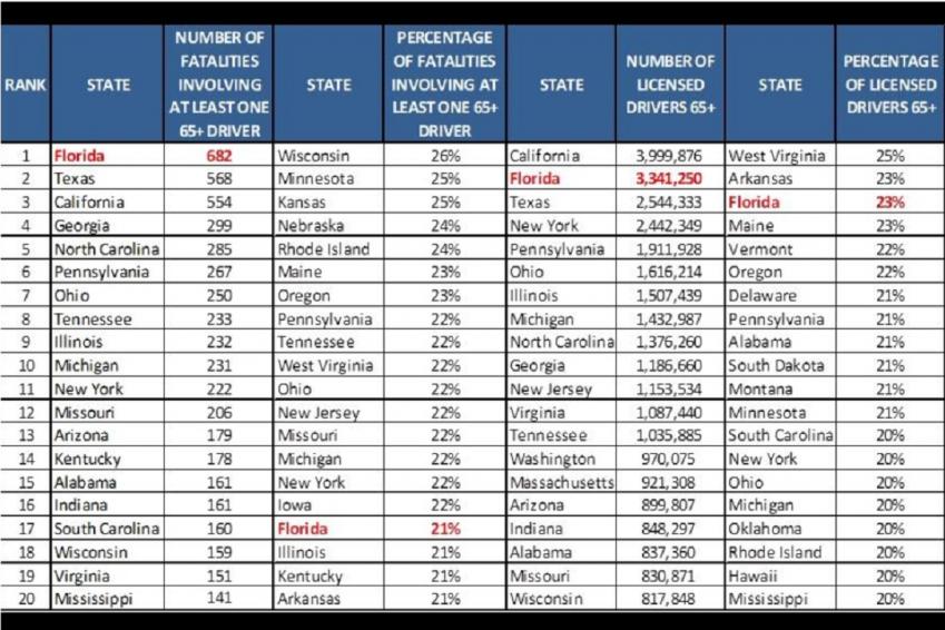
Florida is poised to surpass California and Arizona as the leader in autonomous driving development thanks to an aggressive legislative agenda that began in 2012 and direct engagement with autonomous car developers. The state has good reasons for fostering automated driving given that it is the second largest state in the U.S. with the third highest number of highway fatalities.

These Florida realities and others were brought to my attention by a member of the Florida Chamber of Commerce who I met earlier this year. The Chamber of Commerce is at the heart of the “Autonomous Florida” effort.

There are many motivations for stimulating autonomous vehicle development in a state where the driving environment is heavily influenced by the behavior of aging drivers and tourists. By many measures Florida is the number one tourist destination in the U.S. and Florida is a leader in highway fatalities involving senior citizens.

SOURCE: TRIP Transportation Research

In spite of all this momentum and motivation, The Florida Chamber of Commerce, which has been a leader in the autonomous driving effort, held a Webinar recently that focused on potential job losses and other negative economic impacts from autonomous driving. The Webinar also highlighted varying levels of ambivalence toward the technology from different demographic segments.

The Webinar embodied all the worst boogieman concerns that autonomous driving technology inspires including fear of the vehicles themselves and fear of near-catastrophic job losses from their deployment. The gloomy Webinar contrasts mightily with the otherwise autonomous tech booster-ism of the Florida Chamber.

In fact, Florida is poised to add multiple new autonomous vehicle partners including Cruise Automation and Waymo in coming months, vaulting the state into contention with California and Arizona for leadership in the segment. Florida has done much to lay the ground work including a focus on funding infrastructure investments and setting up multiple smart city and sustainable community initiatives.

The onset of Florida’s leadership is notable as it becomes the third fair weather state – fourth if you include Nevada – to embrace autonomous vehicle tech. Florida is also following the lead of Arizona in clearing away regulations to open up its roads to driverless, steering wheel-less, and brake-and-accelerator-pedal-less automated vehicles.

This is important in the context of countries around the world that are attempting a top-down approach to simultaneously fostering and regulating autonomous vehicles. The message from Florida (and Arizona and Virginia and a growing roster of U.S. states) is: Less is more.

Regulators and legislators are more likely to get things wrong or narrow development options by intervening too aggressively. The onset of autonomy does indeed have implications for infrastructure, employment, productivity and consumer behavior. But regulators and legislators are unlikely to “guess right” when it comes to specifying how technologies are deployed or which technologies are acceptable.

Safety and security are key issues and standards-setting organizations are best equipped to address these concerns. But just as we are exploring allowing drivers to take their hands off the steering wheel, it is probably best that regulators and legislators keep their hands off the technology.

Legislation before the U.S. Congress intended to regulate autonomous vehicle deployments and override state authority is currently stalled, and rightly so. The implementation of autonomous vehicle technology will mean different things in different regions and, thus far, there is no single clear path to autonomy.

California has implemented an array of licensing and data collection obligations. Florida and Arizona, in contrast, do not. Only time will tell which path forward is most attractive, acceptable or swiftest – to say nothing of safest.

States are closer to the action and better able to respond than the Federal government. The National Highway Traffic Safety Administration in the U.S. Department of Transportation has thus far demonstrated it is adequately up to the task of providing basic regulatory support within existing rules. The Society of Automotive Engineers has made its standards-setting contribution and is working closely with the Florida Chamber on autonomous vehicle testing and development.

A study from Germany-based research firm Progenium conferred autonomous vehicle development leadership upon the U.K. based on 23 factors as part of an Autonomous Driving Index. U.K. panelists at a recent London mobility event agreed with those findings in the context of the U.K.’s top-down oversight of autonomous vehicle development.

As for me, I prefer what, to Europeans, must look like a highly chaotic autonomous vehicle development environment ruled, for now, by individual states with some light Federal regulatory oversight. Autonomous driving is a local phenomenon ruled by varying local driving regulations and demographic and meteorological conditions.

Even individual states can get things wrong – particularly when rules become too intrusive. My favorite absurd rule is California’s special licensing for “drivers” of autonomous vehicles. Wait. What? It makes no sense to me.

Florida is on the right path with the right idea. But Florida needs to set aside the confusing messaging around lost jobs and fear of autonomous cars. Autonomous vehicles will create employment, stimulate the economy and change the way people think about transportation generally and driving in particular – and all of that is for the greater good.


eSilicon and SiFive partner for Next-Generation SerDes IP

eSilicon and SiFive partner for Next-Generation SerDes IP
by Daniel Nenni on 08-10-2018 at 12:00 pm

While writing “Mobile Unleashed: The Origin and Evolution of ARM Processors In Our Devices” it was very clear to me that ARM was an IP phenomenon that I did not believe would ever be repeated. Clearly I was wrong as we now have RISC-V with an incredible adoption rate, a full fledged ecosystem, and top tier implementers which now includes eSilicon.

I spoke to Mike Gianfagna and Lou Turnullo from eSilicon about their recent announcement. A small world story, Mike and I worked together at Zycad and Lou and I worked together at Virage Logic. Virage took over the Zycad building so my commute did not change nor did the color of my office. Mike and Lou are very approachable guys with a wealth of experience so if you have the opportunity, definitely approach them.

This announcement is really about SerDes which has changed quite a bit over the years. You will be hard pressed to find a leading edge chip without SerDes inside so this is a big semiconductor deal, absolutely. Earlier SerDes were analog. In an analog SerDes, all characteristics of the SerDes are “hard coded” and cannot be changed. Newer SerDes are more complex and must operate in a wider variety of system configurations. These SerDes are often DSP-based vs. analog.

The eSilicon SerDes is DSP-based. With this architecture you can control characteristics of the SerDes via firmware. This is what the SiFive E2 embedded processor is used for. New SerDes must operate in a wide variety of system configurations – backplane configurations, temperature/humidity extremes, connector types. All this requires configuration of the SerDes equalization functions so the SerDes will match its operating environment so it can deliver the best power and performance.

Bottom line:
DSP-based SerDes can be “tuned” to the operating environment whereas analog SerDes cannot. Another interesting application is continuous calibration which is also possible, where the SerDes can be tuned and re-tuned over time to adapt to changes in the operating environment and even changes in the SerDes itself as it ages.

eSilicon and SiFive put out a good press release so I have included it here. You can read more about the SiFive E2 Core HERE.

eSilicon Licenses Industry-Leading SiFive E2 Core IP for Next-Generation SerDes IP
Configurability of industry’s lowest-area, lowest-power core provided optimal solution for eSilicon

SAN MATEO, Calif. and SAN JOSE, Calif. – Aug. 7, 2018SiFive, the leading provider of commercial RISC-V processor IP, and eSilicon, an independent provider of FinFET-class ASICs, market-specific IP platforms and advanced 2.5D packaging solutions, today announced that, after extensive review and testing of available options in the market, eSilicon has selected the SiFive E2 Core IP Series as the best solution for its next-generation SerDes IP at 7nm.

eSilicon’s 7nm SerDes IP represents a new breed of performance and versatility based on a novel DSP-based architecture. Two 7nm PHYs support 56G and 112G NRZ/PAM4 operation to provide the best power efficiency tradeoffs for server, fabric and line-card applications. The clocking architecture provides extreme flexibility to support multi-link and multi-rate operations per SerDes lane.

“Today’s high-performance networking applications require the ability to balance power and density to effectively address increasing performance demands,” said Hugh Durdan, vice president of strategy and products at eSilicon. “SiFive’s E2 Core IP allows eSilicon to provide the flexibility and configurability that our customers require while achieving industry-leading power, performance, and area.”

The SiFive E2 Core IP is designed for markets that require extremely low-cost, low-power computing, but can benefit from being fully integrated within the RISC-V software ecosystem. At one-third the area and one-third the power consumption of similar competitor cores, the SiFive E2 Core series is the natural selection for companies like eSilicon that are looking to address the challenges of advanced ASIC designs.

“eSilicon has a successful track record for leveraging the most advanced technologies to develop high-bandwidth, power-efficient IP for ASIC design,” said Brad Holtzinger, vice president of sales, SiFive. “Our E2 Core Series IP takes advantage of the inherent scalability of RISC-V to bring the highest performance possible to the demands of advanced ASICs. We look forward to working with eSilicon on its next-generation SerDes to address these demands.”

About SiFive
SiFive is the leading provider of market-ready processor core IP based on the RISC-V instruction set architecture. Led by a team of industry veterans and founded by the inventors of RISC-V, SiFive helps SoC designers reduce time-to-market and realize cost savings with customized, open-architecture processor cores, and democratizes access to optimized silicon by enabling system designers to build customized RISC-V based semiconductors. SiFive is located in Silicon Valley and has venture backing from Sutter Hill Ventures, Spark Capital, Osage University Partners and Chengwei Capital, along with strategic partners Huami, SK Telecom, Western Digital and Intel Capital. For more information, visit www.sifive.com.

About eSilicon
eSilicon is an independent provider of complex FinFET-class ASICs, market-specific IP platforms and advanced 2.5D packaging solutions. Our ASIC+IP synergies include complete 2.5D/HBM2 and TCAM platforms for FinFET technology at 16/14/7nm as well as SerDes, specialized memory compilers and I/O libraries. Supported by patented knowledge base and optimization technology, eSilicon delivers a transparent, collaborative, flexible customer experience to serve the high-bandwidth networking, high-performance computing, artificial intelligence (AI) and 5G infrastructure markets. www.esilicon.com


Desperation Drives Inspiration

Desperation Drives Inspiration
by Daniel Nenni on 08-10-2018 at 7:00 am

This is the tenth in the series of “20 Questions with Wally Rhines”

1978 was a bad year for TI. In April, Intel announced the 8086 followed by disclosures of 16-bit microprocessors from Motorola, the 68000, and Zilog, the Z8000. TI had tried to leapfrog the microprocessor business by introducing the TMS 9900 16-bit microprocessor in 1976. But the TMS 9900 had only 16 bits of logical address space and the industry needed a 16-bit microprocessor for address space rather than performance. In addition, TI had no peripheral chips for the TMS 9900 and tried to overcome that weakness with an 8-bit bus version of the 9900 called the 9980 (an approach that Intel also followed with the Intel 8088) but TI found that any performance advantages of a 16-bit microprocessor were sacrificed with the 8-bit approach (https://spectrum.ieee.org/tech-history/heroic-failures/the-inside-story-of-texas-instruments-biggest-blunder-the-tms9900-microprocessor). Intel overcame that weakness by winning the design socket for the IBM PC with the 8088 despite the performance weakness.

TI also tried to develop a 16-bit TMS 9940 microcontroller with a whole new set of problems resulting in resignation or termination of much of the microprocessor team. I became manager of the TI microprocessor activity more because nobody wanted the job than through personal merit. But I had a different motivation. At the time, I was engineering manager of TI’s Consumer Products Group, heading the design of calculator chips, Speak ‘n Spell speech processors and other miscellaneous devices. That job was located in Lubbock, Texas, which was not my idea of a great location for a 31 year old single male. So Houston, which had some drawbacks, scored far above Lubbock in my plan. Most of my time in Houston was initially filled by exit interviews with all the people who were bailing out of the sinking ship. Fortunately, there were some resilient, smart people like Kevin McDonough, John Hughes, Jeff Bellay and Jerry Rogers (who later founded Cyrix and married Jodi Shelton, Founder and CEO of GSA). John Hughes convened a day-long meeting to debate what would be important after host microprocessors since we had obviously lost that race.

The answer: Special purpose microprocessors. We chose three and then added a fourth one later, and named them the TMS 320, 340, 360 and 380. The TMS 320 was a communications processor, the 340 graphics, the 360 mass storage. Later the TMS 380 was designed for the IBM Token Ring LAN. The first job was to decide what a communications processor, or Signal Processing Microcomputer, as we called it, would be. Ed Caudel spent the next six months analyzing that question and concluded that the distinguishing characteristic was a single-cycle multiply/accumulate instruction (although we required two cycles in the first generation TMS 32010 but made it to one cycle with the 32020). John commissioned Kevin and others from systems groups around the company to write applications using alternative instruction sets. Early on, we found we needed a DSP expert and, fortuitously, our group in Bedford, England had interviewed one named Surendar Magar. Tony Leigh has documented most of the history very accurately. Surrendar quickly determined that the single cycle multiply/accumulate would have to be done in hardware, not software as Ed had hoped. (http://www.tihaa.org/historian/TMS32010-12.pdf(www.tihaa.org/historian/TMS32010-12.pdf).

TI was not the first company to develop a single chip digital signal processor. In fact, it was the fifth. Intel announced one while we were developing the TMS 320 but it incorporated an on-chip 8-bit A/D and D/A making it unusable for most applications. Chi-Foon Chan, Co-CEO of Synopsys, who was working at Intel on the first DSPs, tells me that the poor customer reception of the 2920 caused Intel to kill the enhanced version of the chip, which he was working on, thus keeping the door open for TI.

Despite lots of delays, the TMS 320 was announced at the February 1982 ISSCC with rave revues from people like Ben Rosen, the leading semiconductor analyst. We knew we had a winner but the world didn’t understand digital signal processing. We had to publish books, develop algorithm libraries and promote the technology. Financial analysts paid no attention and neither did our senior management so I found myself giving largely unappreciated presentations at financial and technical meetings as well as in the TI Board room.

We needed some high volume applications and our largest customer was Lear Sigler who was making analog repeaters for under water cables. Hardly a high volume application. We needed consumer products companies in Asia. But our Japanese organization was totally uninterested. Their customers almost always wanted custom chip designs. And then a unique event changed the tide. A group in Canada wrote an application note on how to design a FAX MODEM using a TMS 32010. A group in Australia read the article and built a prototype and sold the design to a Japanese company, Murata.

A Murata engineering manager called the TI Japan office and asked for a quote on the TMS 32010. The TI Product Marketing Engineer had never heard of the TMS 320 but he looked it up in the price book and quoted a $35 price. We had never sold one north of $10 so this was a unique response. The Murata engineer said, “Good. I’ll take 20,000 parts.” From then on, we had no resistance from the TI Japan organization and, in fact, they then designed a derivative named the TMS 320C25 which became one of the highest volume members of the family.

The most strategic discontinuity came later. After years of struggle, we convinced Ericsson to design a TMS 320 into a cell phone. A subsequent need for a cost reduced version of the phone became apparent. We had to combine two ASICs, a TMS 320 DSP and a static RAM into a single chip. “How hard can this be?”, I said. All the parts are already verified. I didn’t understand the laws of verification that drive the need to verify internal state, increasing the amount of verification as the square of the number of gates when you combine chips. I willingly committed to Lars Ramquist, the CEO of Ericsson, that we would do the design quickly. A crash effort resulted and, in parallel, Gilles Delfassy took on a similar task for Nokia.

Fortunately, the chips worked and TI grew the wireless baseband MODEM business to something approaching $4 billion per year. The subsequent step was even more critical. To do similar low cost designs for all the other producers of cell phones (and other applications like hard disc drive controllers), we needed to combine our ASIC library with our embedded DSP. Everyone told me that this would be suicide. ASIC’s were sold as cents per gate while DSP’s had high gross margins. But Krishna Balasubramanian (known as Bala) and I decided to combine the ASIC and microprocessor business into one group under Rich Templeton. A good decision. Success followed, DSP-based technology became nearly half of TI’s revenue and Rich eventually became Chairman and CEO. In between, Tom Engibous leveraged the technology to create a wide variety of businesses while building TI’s position in analog. In 2017, TI became the most profitable of the major semiconductor companies in the world at 41% operating profit.

The 20 Questions with Wally Rhines Series


Living on the (IoT) Edge

Living on the (IoT) Edge
by Tom Simon on 08-09-2018 at 12:00 pm

The phrase “where the rubber meets the road” is especially apt when it comes to discussions about the Internet of Things. The obvious interpretation is that dissimilar things are being put together in a mutually dependent fashion. When I hear the phrase I always think of the things that can go wrong, such a tire sliding instead of sticking to the road. In the world of IoT development there are plenty of parallels. Most often we are talking about dissimilar worlds – physical and digital, and the challenges of combining them. Just as in tire (or road) design, there are plenty of limitations that make the task of building effective IoT devices more difficult.

The classic model is for an IoT edge device to have one or more sensors, on-board processing power and the means to connect to the internet – usually wirelessly. All the familiar limitations apply, such as low power requirements, performance/cost tradeoffs, packaging, etc. The first step is to develop a proof concept, which, while useful, may omit the evaluation of many key performance characteristics. So, what happens next? This is the question that Mentor seeks to answer in their recent white paper entitled “Proof-of-Concept: The Day After”, by Jeff Miller, Product Marketing and Strategy.

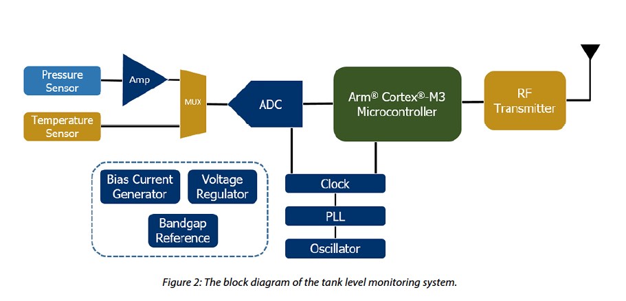
In the white paper, Jeff takes us through the steps of development for a tank fluid level monitoring system. This would have wide applicability in breweries, wineries or other beverage facilities, for a start. For instance, it could be used to detect if fluid levels were dropping due to a leak. Mentor’s example system consists of a pressure sensor which could then be used to infer the height of fluid above the sensor. It has an analog to digital converter that is connected to a processor. There is also an RF transmitter to provide internet connectivity. In the proof of concept, that they prepared prior to the prototype stage, they used a voltage reference instead of the actual pressure sensor. In the prototype, there are a number of supporting circuits, including an oscillator, PLL and clock which is used by both the processor and the ADC.

For the prototype, they used a MUX to add the option of including a temperature sensor in future versions. In the whitepaper, they go through each step to design a fully working system. To ensure high sensitivity they employed a Wheatstone bridge to help measure the change in resistance in the sensor. They instantiated all the elements of the design and then performed simulations. They opted to use an ARM Cortex M3 instead of an M0. This was done mostly to provide more flexibility in the final system, but was easily possible because the development IP for both processors is available under the ARM DesignStart program. They used the CodeBench development system which also supports both processors.

With the software written, a system simulation is possible. The whitepaper shows the steps involved in this. Lastly the communication block is brought in. With bidirectional communication, cloud services or a web front-end can be implemented. Also over the air updates would be possible with bidirectional communication.

To complete a prototype project like this, a suite of tools is needed that covers custom IC design, PCB, embedded software, and system simulation. Mentor offers a complete design flow like this that is tailored for the needs of IoT Edge Device developers. That coupled with the easy access to ARM processors, suitable for these kinds of applications, dramatically simplifies the design and development process. At the end of the day all of the system’s the performance characteristics need to be fully optimized to develop a competitive product that provides differentiation in the marketplace. The detailed whitepaper is available for download on the Mentor website.


Machine Learning with Prior Knowledge

Machine Learning with Prior Knowledge
by Bernard Murphy on 08-09-2018 at 7:00 am

I commented recently on limitations in deep learning (DL), one of which is the inability to incorporate prior knowledge, like basic laws of mathematics or physics. Typically, understanding in DL must be inferred from the training set, which in a general sense cannot practically cover prior knowledge. Indeed one of the selling points of DL is that it doesn’t need to be programmed with algorithms; intelligence is inferred entirely from these training sets through a form of optimization. This works well when the training set is large enough to cover the most important aspects of an objective but not so well when other variations are introduced, such as rotations or movement. That’s a rather big limitation.

The brute-force way to solve this problem is to expand the training to cover more variations. For rotations, instead of N training samples, perhaps you need 108*N to cover 3 axes of rotation and 36 orientations in each axis (0, 10, 20, … degrees). That’s a massive increase in the number of training samples you have to gather and label. For movement, how do you train ML to determine what will happen to all the other balls on a snooker table when you strike the cue ball? Using training to rediscover what Newton codified over 300 years ago seems like a huge waste of ingenuity.

The best way to handle these variants is to use prior knowledge in math and physics, combined with ML. In computer graphics we infer the impact of rotations on a view using algorithms based on math formulae. In the snooker example, we use Newton’s laws of motion, again encoded in algorithms. Those laws/algorithms capture in a few simple equations what would otherwise require perversely large training sets in the pursuit of algorithm-free recognition. So much for banishing algorithms.

One paper from Stanford uses an understanding of projectile mechanics to identify and track the path of a pillow thrown across a room. As far as I can tell, they model recognition in short segments of the path first, then use constraints to penalize complete paths which don’t follow the expected second-order equation of motion. In effect they are using a classical formula as a constraint in the structure of a neural net. This work shows some promise for learning in such contexts with only weak supervision.

Another interesting paper from the Institute of Science and Technology in Austria takes a different approach to build (through ML) models for safe operating conditions for robots (such as ranges of moving arms or legs) based on learning simple formulae from operations in a known-safe range. These formulae then allow extrapolations beyond the trained range. They describe this as “a machine learning method to accurately extrapolate to unseen situations”, in effect building its own prior knowledge in the form of simple linear equations through experiments in a more bounded space.

A third example from the Sorbonne University provides an illustration of forecasting sea-surface temperatures (SSTs). Surface temperature data is already generated through satellite imagery, providing vast amounts of current and historical information. Forecasting how this will develop requires evolving this data forward in time based on partial differential equations (PDEs) and is the basis for the standard approach to forecasting using numerical solution methods. This research team instead uses a CDNN with discretized version of the PDE equations to guide weighting in time-propagation in the net. Their work shows promising results in comparison with numerical methods and some other NN approaches.

So, two methods which reduce/discretize prior knowledge (physics) to mechanisms which fit into existing deep learning architectures through weighting and one which derives simple equations to form its own “prior” base of knowledge. Intriguing directions, though for me the Sorbonne approach seems the most extensible since almost all problems in physics can be reduced to PDEs (though I guess the geometry of present-day neural nets will limit application to 2 dimensions, plus time).


Enhancing Early Static FSM

Enhancing Early Static FSM
by Alex Tan on 08-08-2018 at 12:00 pm

Finite state machines (FSMs) are widely adopted as part of reactive systems to capture their dynamic behaviors using a limited number of modes or states that usually change according to the applied circumstances. Some terminologies are frequently used to describe the FSM characteristics: state, transition, condition and sequences. A state defines the behavior and may produce action or output; a transition describes change involving of state(s); a condition allows transition to occur; and a sequence is comprised of a set of two or more transitions.

FSM can be categorized in term of its output transition. A deterministic FSM, if it has only one transition to next state; while a non-deterministic FSM has more than one possible next state for each pair of current state and input vectors. For practical applications, FSMs can be grouped based on how their outputs are defined. Moore FSM is the state machine whose output are a function of the current state only, while a Mealy FSM has its output and next state dependent on both the current state and input(s).

Many of the FSM practical applications such as in communication systems, crypto-processing, visual processing and as part of the embedded controllers are implemented using various schemes, from a static to be more reconfigurable styles –depending on if it is internally initiated (self-reconfigurable) or driven by external reconfiguration events.

Aldec and Verification of FSM
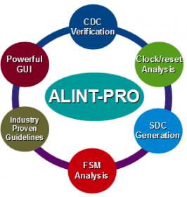
As an industry leader in Electronic Design Verification, Aldec’s solutions include a verification strategy in ALINT-PRO™ that is comprised of three key elements: static structural verification, design constraints setup, and dynamic functional verification.

The first two steps are executed in ALINT-PRO, while dynamic checks are implemented via integration with Aldec’s simulators Riviera-PRO™ and Active-HDL™ (ModelSim® is supported) based on the automatically generated testbench.

Previously, designers had to deal with debugging the FSM late in the implementation stage such as by using Riviera-PRO advanced verification platform as illustrated in the following diagram:

“Most issues designers face when implementing FSM-based control blocks tend to be caught during RTL-signoff, using coverage-enabled simulation and/or formal property checking methods,” observes Sergei Zaychenko, Aldec Software Product Manager.

In response to the increasing verification challenges for complex designs, Aldec has expanded the rule-checking capabilities of its popular ALINT-PRO™ tool. it has enhanced the tool to include twice as many FSM checks and new graphical representations to aid with state explorations.

“Aldec ALINT-PRO can discover many complex FSM issues long before test stimuli are available. With the latest version of ALINT-PRO™ users can do FSM-level verifications that will save them a significant amount of verification time further on down the line,” added Sergei.

An early FSM static validation can be achieved with ALINT-PRO by taking a two-step approach: first by performing an FSM exploration using FSM graphical environment, and then by applying a complete list of FSM targeted rule checks. ALINT-PRO extracts FSM from a design code and presented in FSM viewer.

To facilitate a better exploration of the extracted FSMs and reveal FSM-based design issues, ALINT-PRO (v2018.07) has an enhanced GUI incorporating checks based on the 25 newly added FSM design rules covering advanced aspects and typical errors. The FSM window acts as the FSM debugging tool that generates state transition graph with color-coded notation signifying transitions among object states. It differentiates a deterministic, non-deterministic, beginning and ending state. Designer could trace a sequence and switch data representation mode from graph to tabular format.

FSM Static Checks and Coding Issues
An event-driven system programming tends to use heavily nested conditional constructs (if-else, switch-case) in order to implement various responses due to a triggering event or a combination of past events in the system. FSM adoption is intended to reduce potential clutters caused by the complex number execution paths, the multitude of variables and the many transitioning between different modes of execution.

ALINT-PRO identifies FSM related bugs including unreachable, deadlockand redundantstates which are the common types of shortcomings faced by designers while capturing the FSM RTL codes. An unreachablestate is not reachable from any initial state of the FSM but has output to transition; while a deadlockstate is reachable but once entered indefinitely unable to change its state; and a redundantstate has neither input or output transition from/to.

The FSM type compliance check can be targeted to a pre-defined set of requirements such as to satisfy two combinational and one sequential processes. Additional FSM implementation specific checks such as those related to reset control, FSM state enumeration, state encoding type allocation (binary, gray, onehot, etc.) and other FSM attributes declaration (e.g., fsm_encoding=…) are complementing the over 40 new rules designated for improving the VHDL and Verilog/SystemVerilog RTL coding quality.

To generate a highly reliable design, best-FSM-design-practice type of checks can also be applied. This includes good naming conventions (describing more than one FSM in a single design unit, unique names for states of different FSMs, etc.); FSM should recover in Reset state in case of FSM state variable corruption and use case default with unconditional transition to FSM reset state. Reset state transition handling is crucial such as in autonomous sequential modules of a complex digital system.

Workspace, Project and Heterogeneous Design
In ALINT-PRO environment, the RTL codes, constraints and properties are captured into workspace and projects. An enhanced setup automation for complex Xilinx Vivado and ISE projects is made in 2018.07 release. The extension enables a “push button” flow for early static verification of IP-intensive Xilinx FPGA-targeted designs. A workspace is automatically organized to deliver hierarchical and incremental DRC and CDC analysis, allowing the designer to concentrate on checking custom RTL blocks, while preserving accuracy at the boundaries of IP blocks. Unless an IP block is re-configured in the original design environment, it is only being analyzed once, and the extracted block-level timing constraints are automatically promoted to enable higher level verification of the main design.

To find out more about ALINT-PRO, please check HERE


Tesla Leap of Faith (or the Adoration of Elon Musk)

Tesla Leap of Faith (or the Adoration of Elon Musk)
by Roger C. Lanctot on 08-08-2018 at 7:00 am

The Reverend Elon Musk, CEO of Tesla Motors, held forth to his flock on yesterday’s earnings call. Musk described at length his efforts to lead the company out of production hell. The lengthy session highlighted the challenges facing the company, which posted its greatest quarterly loss ever, and was emblematic of the typical high-flying technology entrepreneur making a big bet against long odds.

Unique to Tesla, though, is the commitment it seeks from both investors and the drivers of its cars. In fact, Musk went so far as to insist that the media and analysts must commit more fully to the company’s vision for achieving mass electrified, sharable vehicle autonomy – or risk being described directly as idiots or worse.

He has no patience for scary headlines which tend to follow the relatively infrequent fatal crashes of Tesla vehicles. He confirmed on the call that the amount of recorded automated driving that occurs in autopilot-equipped Tesla vehicles tends to decline after such reports only to recover later. In Musk’s eyes, these discouraging downturns in autopilot usage only further delay the arrival of full autonomous operation – i.e. the promised land.

Musk also takes issue with the inclination of the press to blame-shame Tesla for pre-emptively releasing data implicating drivers in their own autopilot misadventures, fatal or otherwise. Musk did not mention the growing number of crashes (after all, there are more Tesla’s on the road), fatal and otherwise, that appear to be the result of autopilot shortcomings.

This is where the leap of faith is most difficult to take. Musk and Tesla were on solid ground two years ago (can it be that long?) following the fatal Florida crash. Tesla took multiple steps in response to that event including:

  • Parted with camera system supplier Mobileye
  • Laid blame for the crash upon a misuse of autopilot (on a non-limited access highway)
  • Updated autopilot software and geo-fenced its usability
  • Conducted a study of vehicle data – sharing the results with the National Highway Traffic Safety Administration – demonstrating that vehicle crashes were substantially reduced in Tesla’s equipped with autopilot

Ultimately, the scope of Tesla’s geo-fencing expanded such that it was nearly unlimited thereby completing the transition away from Mobileye. Still the system remains ill-suited to secondary roads and side streets with intersections.

Intermittent crashes continue including a fatal crash in California, once again blamed on driver inattention, along with non-fatal crashes with parked vehicles on highways. One crash stands out from the rest, though, having occurred shortly before the fatal Florida crash.

The crash occurred in China and Tesla was reportedly unable to retrieve the vehicle’s data logs due to the severity of the crash. As a result, the fatal China crash between a Tesla and a truck parked in the high speed lane of a highway, remains unresolved along with pending legal action from the family of the driver.

Given the fact that the China crash occurred before Tesla modified its automated driving system software, it is difficult to conclude whether any findings from that crash will be relevant to understanding how autopilot, as currently configured, functions today. More importantly, in spite of the availability of video from the vehicle, Tesla asserts that it is not possible to conclude that autopilot was operating at the time of the crash.

Infrequent though they may be, Tesla crashes continue to occur. Operating a Tesla in autopilot mode – and, in fact, investing in Tesla – requires a leap of faith. You have to believe in Tesla and Musk’s vision of autonomous operation.

Tesla has not been the only autonomous vehicle operator to experience a fatality. Uber suffered the same fate, though the fatality was a pedestrian not a passenger or driver. In the Uber crash in Tempe, Az., a number of factors were blamed including driver inattention and a malfunctioning or inactive automatic braking system. Some astute observers also noted that a thermal sensor might have aided detection of the pedestrian on the dark road.

Tesla famously makes use of ultrasonic, radar and camera sensors supported by Nvidia processors to analyze and fuse the incoming information and enable automated driving. Also famously, Musk disparages the use of Lidar sensors, which some believe might have prevented both the Florida and China fatal crashes.

An Israeli startup, BrightWay Vision, asserts that its image gating technology, for enhancing camera-based sensor inputs, might have also prevented the China crash. The gating technology might have been able to overcome what is thought to have been radar interference caused by the picket fence-like highway barrier on the left side of the vehicle.

The bottom line: To buy a Tesla or its stock or to operate a Tesla in autopilot mode is to take a leap of faith. It is a leap of faith in the gigafactory strategy, the fast charging network, SpaceX, increases in battery power density, reductions in cost, increases in production and the pursuit of profitability. It is a leap of faith in a CEO who sleeps on the factory floor and occasionally indulges in Tweet storms.

Mainly, it is a leap of faith that the best and most ethical decisions are being made regarding vehicle autonomy. If Musk were CEO of any other car company he would long ago have been crucified by investors, regulators and customers for the handful of fatalities that have occurred in Tesla vehicles. Musk spent a fair amount of time on Wednesday’s call apologizing for his rants and insults from the previous earnings call. What Musk really needs to do is thank his customers – especially those who have adopted autopilot – for their leap of faith.