webinar banner AI 2026 v2

Systems Design vs Integrated Circuit Design

Systems Design vs Integrated Circuit Design
by Daniel Nenni on 09-21-2018 at 7:00 am

This is the sixteenth in the series of “20 Questions with Wally Rhines”

Electronic design automation (EDA) began and grew with the integrated circuit (IC) design business probably because IC design grew in complexity faster than printed circuit boards. The race for superiority in PCB design evolved in parallel, however, and has become increasingly important as system design moves to more advanced EDA.

Daisy, Mentor and Valid, founded in 1980 and 1981, supported a combination of IC and PCB design. Both technologies required schematic capture and layout but simulation was primarily an IC design technology. Mentor and Daisy targeted both IC and PCB design while Valid specialized in PCB. At the same time, companies like Racal Redac (Europe), Cadence, SciCards (on VAX), Intergraph and others competed for the PCB market. As much as the IC market, competitive advantage in PCB design and layout (and eventually manufacturing) resulted from strategic acquisitions as well as organic technology development.


Computervision, Calma and Applicon were the “Big 3” electronic design environments that preceded the Daisy, Mentor, Valid era. But the GE acquisition of Calma, which had a very strong IC layout capability, demonstrated how large companies can easily mismanage the acquisition of fast moving, small, high tech companies, and the value of Calma was quickly lost. Daisy and Mentor went head to head and Mentor ultimately won the majority of the systems companies (and even owns the remnants of Daisy today through Mentor’s acquisition of Veribest from Intergraph), a historical event that gives Mentor its strength today in system design as systems companies (particularly aerospace, defense and automotive) rarely changed EDA suppliers, even as they adopted IC design tools to complement their PCB tools.

A critical shift occurred in the early 1990’s. Mentor’s PCB capability came from the acquisition of CADI. Cadence had acquired tools as well and both Zuken and Racal Redac had strong positions grown from organically developed tools. In 1990, Cadence and Mentor had approximately equal market shares, with Zuken and Racal Redac making up much of the remainder of the PCB market. Cadence made a very bold move, taking advantage of the fact that Mentor was in a period of weakness due to its struggles with Version 8.0. Cadence acquired Valid, announcing that the overlap between Cadence and Valid PCB design tools would be quickly resolved by eliminating the losers and crowning the winners. This turned out to be a difficult strategy since ALL of the users from both Cadence and Valid lost some portion of their design flow. That forced all the Cadence and Valid users into a competitive re-evaluation of all the alternatives. Zuken gained a little and Mentor gained a lot, while Cadence kept some. The result: By 1999, Mentor had 20% of the PCB market, Cadence 17% and Zuken, who had acquired Racal Redac to complement its Japan strength with a European supplier, had 16%. By this time, the dot com crash was beginning and Zuken reduced investment while Cadence focused on IC design. Mentor, who was still troubled by the Version 8.0 problems, continued a heavy rate of investment in “system design” including PCB, as an area of #1 market strength, and continued to gain market share in PCB, peaking at a market share of about double its nearest competitor.

Over the next two decades, all this history had an effect on strategic evolution. The original companies that needed to move toward EDA standardization in the 1980’s were largely systems companies. They needed standardization in design methodologies, libraries and tools across their disparate divisions. Even though two thirds of Mentor’s revenue ultimately came from IC design, the original adopters of EDA remained as a stable base of customers, particularly those who manufactured cars, planes and trains, or were involved in aerospace and defense. Mentor was able to capitalize upon that large market share and, thanks to some developments along the way, developed a leading position in electronic wiring and embedded software for those kinds of systems.

As much as anything, this systems capability is what made Mentor so attractive to Siemens’ software division as they looked to extend their “digital twin” platform from design, product life cycle management, mechanical CAD and manufacturing simulation to the electronic dimension of the digital twin.

There was another reason that Mentor’s system design businesses succeeded despite the difficulties of the Falcon Version 8.0 transition. Russ Henke, who managed the PCB business at that time, did not believe that Version 8.0 would ever work. So he followed a path, common in many companies, of quiet non-compliance. He instructed his PCB team to develop a “wrapper” to interface to Version 8.0, just in case it worked, and then proceeded to invest in the traditional PCB design business, consistently growing PCB revenue throughout the period of Version 8.0 chaos and into the 1990’s.

There was another beneficial offshoot of the Version 8.0 transition problems. The Mentor sales force had very little to sell after the announcement that Version 7.0 would not be extended but would be replaced by Version 8.0 whenever that environment became available. An innovative sales team working with the “Value Added Services” group sought out new users for the existing products that were not affected by the Version 8.0 transition. PCB schematic capture was one of those products. They found a local customer in Portland, Freightliner, who manufactured trucks and is now owned by Daimler. Convincing them to move from manual wiring design to EDA can’t have been easy but they became the first adopters of a “field-developed” product named “LCable”, a name that reflected its use in the design and verification of cabling and wire harnesses for trucks and cars. Adoption by other automotive and aerospace companies proceeded slowly but, over the decade starting in 1992, the complexity of automotive and aerospace electronics increased so much that the need for EDA became apparent. By year 2000, the business was blossoming but had outgrown its original roots in PCB design and layout. Martin Obrien joined Mentor from Raychem and brought with him a detailed knowledge of how automotive, aerospace and defense companies thought about electrical wiring architectures. That became one of the valuable core businesses of Mentor over time. Today, the “Capital” family of integrated electrical system design products has become the leading system connectivity design environment, extending from concept through simulation, topology, bill of materials, factory form boards for manufacturing and maintenance after the sale. Siemens has become a teaching customer but the Capital family is intensely focused on providing an open environment that can help Siemens’ competitors as much as it helps Siemens.
The 20 Questions with Wally Rhines Series


Apogee Pipelining in Real Time

Apogee Pipelining in Real Time
by Alex Tan on 09-20-2018 at 12:00 pm

Pipelining exploits parallelism of sub-processes with intent to achieve a performance gain that otherwise is not possible. A design technique initially embraced at the CPU micro-architectural level, it is achieved by overlapping the execution of previously segregated processor instructions –commonly referred as stages or segments. Pipelining for timing fixes has become mainstream option in design implementation space, especially when designers had exhausted other timing closure means at the physical design step (such as optimizing wire utilization or resource sharing in the logic cone).

Anatomy of pipelining
Pipeline involves the use of flip-flop and repeater insertion –although some designers tend to focus on flip-flop insertion part, as it is assumed that the implementation tools are to perform repeater insertion by default (such as during synthesis stage or placement/route optimization).

Ideal pipelining should consist of equal stage latency across the pipeline with no resource sharing between any two stages. The design clock cycle is determined by the time required for the slowest pipe stage. Pipelining does not reduce the time for individual instruction execution. Instead, it increases instruction throughput or bandwidth, which can be characterized by how frequent an instruction exits the pipeline.

Pipelining can be applied on either the datapath or control signals and requires potential hazards monitoring. Ideally speaking, pipelining should be done closer to the micro-architectural step as adding flip-flops further down the design realization translates to perturbing many design entities and iterating through the long implementation flow.

SoC Design and Pipelining Challenges
With the recent emerging applications such as AI accelerators, IoT, automotive and 5G, two top challenges encountered by the SoC design teams are scalability and heterogeneity. The former demands an increased latency in the design, while the later requires a seamless integration of interfaces and models.

In the context of timing closure, there are two entry points for injecting pipelining to manage latency. The first is done post static timing analysis (STA). By identifying large negative slack margin among logic stages, designers could provide concrete data points to the architecture team (or RTL owner) for pipelining. This reactive step may be costly if excessively done as implied iteration to the RTL-change translates to resetting the design build.

On the other hand, pipelining can be also performed early on the RTL codes, during micro-architectural inception. While doing it at this stage provides ample flexibility, code architect tends to be conservative due to lack of an accurate delay estimation and being critically aware of increased flop usage impact to the overall design PPA. Hence, some designers have adopted a semi-manual method. It involves rule-of-thumb formulas combined with some SPICE simulations and spreadsheet tracking to arrive at pipeline budgeting plus an involved placement constraints to manage its implementation. This approach is tedious, iterative and prone to over-design as it may include guard-banding to cover backend optimization inefficiencies such as detours due to placement congestion or wire resource shortages.

Avatars and automatic pipelining
At DAC 2018 designer/IP track poster session, Avatar and eSilicon showcased the outcome of their collaboration in achieving successful pipelining through the use of automatic stage-flop insertion performed by Avatar’s Apogee. Avatar Apogee is a complete floor-planning tool that enables fast analysis of design hierarchy and early floorplanning exploration. It shares common placement, routing, and timing engines with Aprisa, the block level, complete placement and route tool (please refer to my earlier blog for other discussion on these tools). Based on its customer feedback, Avatar has introduced in its 18.1 release an automatic pipeline flip-flop insertion feature. This feature automatically adds stage flops on feedthrough nets during floorplanning stage using Avatar’s Apogee new command insert_stage_flop.

Delving further into the feature, first the long top level nets are routed by Virtual Flat Global Router by taking into account any existing congestions, blockages and macros inside the hierarchical partitions. Next, feedthroughs are assigned to the appropriate partitions and stage flops are added based on user specification that includes distance or flop count.

Similar to the mainstream method of pushing buffer into the hierarchy, after its addition the pipeline flops will be pushed into its hierarchical partition with the push_cell command. Subsequently, the module level netlist are automatically updated with the new hierarchical cell instance and the corresponding port gets created at this level as illustrated in Figure 3.

Results and Comparison

Using a large Mobile SoC design as a test case and Apogee’s automatic approach, the design was implemented and routed. The tabulated results show that there were 18% fewer stage flops needed and a 22% saving in flip-flop power with minimal DRC and timing violation (significant reduction in both TNS and WNS slacks).

The total process takes about 2 hours to auto-insert as compared to 3 weeks of manual efforts and multiple iterations to reach to the final flop count. On top of that, timing and routability were challenging with the manual approach. With Apogee, timing and congestion aware automatic placement ensure both routability and timing convergence of the design.

In summary, designers can use Apogee’s new automatic stage flop insertion feature to reduce iterations and also get better stage flop count leading to lower sequential power. The flow also supports netlist update and reports that simplifies downstream formal verification process. According to Avatar Integrated Systems, it plans to expand the capability to auto insert or delete pipeline flops at the block-level placement optimization step in Aprisa –to further improve QoR at block level.

For more details on Avatar’s Apogee please check HERE and Aprisa HERE.


Supporting ASIL-D Through Your Network on Chip

Supporting ASIL-D Through Your Network on Chip
by Bernard Murphy on 09-20-2018 at 7:00 am

The ISO 26262 standard defines four Automotive Safety Integrity Levels (ASILs), from A to D, technically measures of risk rather than safety mechanisms, of which ASIL-D is the highest. ASIL-D represents a failure potentially causing severe or fatal injury in a reasonably common situation over which the driver has little control. Certification to one or more of these levels requires demonstrating that a system can guarantee better than a specified probability of failure, generally requiring increasing levels of failure mitigation, analysis and supporting documentation with each level.

Semiconductor component providers have opted in many cases for certification to component levels below D for cost and/or time-to-market reasons. But this is changing. As electronic content in our cars is increasing, distinctions between what does and does not critically affect safety are blurring. An ECU that might be used in an ASIL-B function today could become interesting for use in an ASIL-D function next year. Consequently, OEMs are extending their demands for ASIL-D certification across more components, to ensure they’re covered no matter what the application.

This ramps up effort demanded in safety assurance in more designs. Certainly component functions must demonstrate mitigation to an appropriate level, but also special care is needed in integrating those components together, commonly through a NoC interconnect. There are three approaches that designers can take to ASIL-D compliance for that network-on-chip:

  • Complete replication (in this case the NoC), either duplication with comparison checks which will report a failure (where it is sufficient to warn the driver that a function has failed) or triplication with majority voting where a failure in one function can be overridden by outputs from two good functions (where simply knowing a system has failed is not enough). Still, complete duplication or replication of a NoC would be a very expensive option.
  • Another acceptable approach is to provide path diversity. If a component fails in one path, there should be other paths through which system operation can continue to work, possibly after updating routing tables. In effect the system can heal around bad nodes and continue to operate. The challenge here is that the designer must prove that all possible paths have backup paths, again likely to be expensive. A second consequence is that performance impact from possible rerouting has to be characterized, potentially as rigorously as for the good part. And finally updating the routing is a software function which will take time and adds further risk, and that must also be characterized and mitigated.

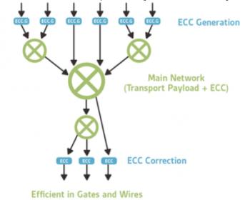
  • A less expensive and disruptive approach is to replicate only those functions within the NoC that must be replicated, such as control blocks, and to use ECC on interconnect wires to correct single-bit errors and flag 2-bit errors. This approach still meets the ASIL-D requirement, avoids all the complications associated with path diversity and has limited area overhead since control blocks represent a relatively small percentage of the overall NoC area.

For a way to meet these new stringent requirements, the last method above is difficult to beat. Adding 8-bits of ECC to a 64-bit link increases the size of the NoC by a little over 10%, versus doubling the size if duplicating the NoC. The solution is entirely in hardware and errors are corrected instantaneously with no need for software reconfiguration and no extra latencies. Finally, validating fault coverage and building a comprehensive FMEDA for the configured network can be completed with existing tools, compared with a path diversity approach which would require analysis over both hardware and network reconfiguration software.

To learn more about Arteris solutions for ASIL-D-compliant NoC interconnect, go HERE.


Semiconductor IP Reality Check

Semiconductor IP Reality Check
by Daniel Nenni on 09-19-2018 at 12:00 pm

A robust, proven library of IP is a critical enabler for the entire semiconductor ecosystem. Without it, ASIC design is pretty much impossible, given time-to-market pressures. Said another way, designing IP for your next chip simply doesn’t fit the schedule – most teams have barely enough time to integrate and validate pre-existing IP. Without solid IP coverage, new process nodes also become somewhat irrelevant for the same reasons. So, designers and foundries care about IP a lot.

7nm is where a lot of the action is these days regarding IP delivery. Datacenter, networking, AI and 5G infrastructure all have a thirst for the power and performance delivered by this node. So, there are lots of claims out there regarding 7nm IP. “World’s first, industry-leading, silicon-proven, robust” are just some of the words you’ll find in all the marketing material available for 7nm IP. The question is, how do you separate the hype from reality, and more importantly how do you truly reduce risk?

Simulation results, silicon data and number of tape outs are all important parts of the homework needed to find IP that is truly “robust”. Lately, there is another dimension to the problem worth considering as well. Beyond the IP working in silicon, does all the IP work well together? Before you bet the farm on your next 7nm design project, are you confident that all the IP will play well together? A completely validated library of IP can still cause huge headaches of it all doesn’t work together. Integration risks are very real, as are the risks associated with modifying IP to hit the required power, performance or area target.

The concept of IP that works well together and supports customization for a target application makes a lot of sense. Recently, eSilicon announced two such IP offerings for data center and AI chips, which SemiWiki covered here. eSilicon calls the concept an “IP platform”. I’m sure other marketing terms will emerge.

Recently, there have been a couple of announcements from eSilicon that bring these platforms closer to home. It turns out a high-performance SerDes is a critical enabler for both platforms. Last week, eSilicon announced very encouraging results from the silicon validation of its 56G 7nm SerDes. Their press release stated: “… lab measurements confirm that the design is meeting or exceeding the target performance, power and functionality. Based on these results eSilicon has begun to demonstrate its test chip to key customers.” So, contact eSilicon if you want to see what their SerDes can do, first hand.

This week, eSilicon announced that theirneuASICä platformis available for customer designs. Some detail about the what’s in neuASIC were disclosed:

“The neuASIC IP platform has been through several 7nm tapeouts. The platform includes the following compiled, hardened and verified functions:

  • Configurable multiply-accumulate (MAC) blocks
  • Single-port SRAM
  • Pseudo two-port and pseudo four-port SRAM
  • Ternary content-addressable memory
  • Pitch match memory
  • GIGA memory
  • WAZPS (word all zero power saving) memory
  • Transpose memory
  • Re-mapper – low power cross-bar
  • Convolution engine
  • 56G SerDes
  • HBM2 PHY

The platform also provides a software AI Accelerator Builder function that provides PPA estimates of the chosen ASIC architecture before RTL development starts.”

So, another reason to contact eSilicon if you’re considering a 7nm AI ASIC. I would check out both of these platforms if you want to reduce integration risks, absolutely.

Also read: eSilicon Announces Silicon Validation of 7nm 56G SerDes


Integrated Power Management IP to Decrease Power and Cost

Integrated Power Management IP to Decrease Power and Cost
by Eric Esteve on 09-19-2018 at 7:00 am

This blog is the synthesis of a white paper “New Power Management IP Solution from Dolphin Integration can dramatically increase SoC Energy Efficiency”, which can be found on Dolphin Integration web site.

The power consumption generated by complex chips was not a real issue when the system could be simply plugged in the wall to receive electricity. The most important feature used to be raw performance, expressed in GHz or MIPS, and was used to market PC to end-user, for example.

Nevertheless, with the huge adoption for wireless mobile devices in the 2000 and later, the metric has changed. For battery powered devices, the time between two battery charge became almost as important as the MIPS power delivered by the phone/smartphone. That’s why efficient but costly external power management solution (7$ for the iPhone 6, up to $14 for the iPhone X) have been implemented in smartphone.

With the massive adoption of battery powered system expected in IoT, industrial or medical, power efficiency is becoming a mandatory requirement, together with low system cost. To reach these goals, SoC will have to be architectured for low-power and integrate power management IP on-chip.

In fact we realize that power consumption is also becoming a key concern in automotive application (ADAS) or sever/network infrastructure. These applications will have to be much more energy efficient, for different reasons like reliability (automotive) or cost (raw electricity and cooling cost in data center). In short, the entire semiconductor industry will have to offer more energy efficient devices, at the right cost. The way to do it is through defining power aware architecture and design chips integrating power management IP.

In this white paper “New Power Management IP Solution from Dolphin Integration can dramatically increase SoC Energy Efficiency”, Dolphin Integration has reviewed all the solutions available to decrease SoC power consumption. The first technique is to define and manage power domains inside the SoC, well-known in the wireless mobile industry, but other techniques can be considered.

Dynamic voltage frequency sclaing (DVFS), near threshold voltage, body biasing, globaly asynchronous localy synchronous (GALS) are also reviewed and discussed in this paper. But a low-power SoC has much smaller noise margin, and special care must be taken to preserve signal integraty in this SoC. In other words, you need experts to support you when implementing these new power management solutions.

In the second part of the paper, the author explains how implementing power management IP in customer’s SoC. The design team has to start from the architecture level to define “power-aware” SoC architecture.The the first task for the designer will be to identify the various functions belonging to the same power domain. This power domain is not simply defined by voltage, but in respect with the functionality of the various blocks expected to be part of the same task in a given power mode.

Once you have split the chip in power islands (memory, logic, analog, always-on, etc.) it’s time to control, gate (power gating, clock gating) and distribute power and clock in the SoC. This will be done by implementing the various power management IPto power the SoC core, and the designer will select controlling power switches, VREG or Body Biasing generator and clocks gating anddistribution, all part of the power network IP port-folio from Dolphin Integration.

The implementation of the SoC power mode control is made straight-forward, thanks to a modular IP solution (named Maestro). This power mode control IP is equivalent to an external Power Management IC (PMIC), similar to those integrated in a smartphone. Maestro will manage start-up power sequence, power mode transition and optimize the power regulation network.

Dolphin Integration claim offering faster TTM and lower cost for customer selecting their power management IP solution, instead of trying to design a low-power SoC on his own. As the design team implement the power management controller (Maestro) as an IP in the SoC, the sytem BOM is lower than using an external PMIC controller (remember the impact of PMIC on the iPhone 6 and X BOM).

Faster TTM is made possible, thanks to technical support from expert engineer, from top level (power-aware architecture definition) to design phase (implementation of the various power management IP). This expertize in low-power design will allow escaping traps, like new noise issues due to mode transition for a SoC partitioned in power domains, or signal integrity suceptibility to crosstalk when operating at extremelly low voltage level.

In the Moore’s law golden age, a chip maker had just to re-design to the next technology node to automatically benefit from higher performance and lower power consumption-at the same time. Today, the semiconductor industry is addressing new applications like edge IoT, medical wearable devices and many more, requiring low-cost IC probably designed on mature technology nodes.

Frequently battery powered, these SoC require an ultra-low power consumption, which can only be reached by using power management techniques. In this white paper, Dolphin Integration describes these new techniques and how to implement power management IP from the architecture level down to the back-end. This is not an easy task, especially when doing it for the first time. That’s why the SoC design team need technical support from low-power design experts and a silicon proven IP portfolio to release an energy-efficient device, on line with the time to market requirement.


To see the White Paper, go to this link

ByEric Esteve fromIPnest


Beyond DRC and LVS, why Reliability Verification is used by Foundries

Beyond DRC and LVS, why Reliability Verification is used by Foundries
by Daniel Payne on 09-18-2018 at 12:00 pm

Reliability of ICs isn’t a new thing, because back in 1980 I was investigating why a DRAM chip using 6um technology was having yield loss due to electromigration effects. I recall looking through a microscope at a DRAM layout and slowly ramping up the Vdd level then suddenly the shiny aluminum interconnect started to change colors and actually bubble because of the high currents, then the metal evaporated. We never could identify the cause of that reliability failure, so it’s kind of haunted me all of these years.

IC designers today will start out a new project by requesting the foundry files for DRC (Design Rule Check), LVS (Layout Versus Schematic) and PEX (Parasitic EXtraction) so that they can perform physical verification tasks to ensure high-yielding silicon and meet timing specifications. In addition to these checks there are an increasing number of reliability checks that need to be done, like:

  • ESD (Electro Static Discharge)
  • LUP (Latch-up)
  • Interconnect reliability
  • Electrical overstress

The number one foundry is TSMC, so no surprise that they have also been at the forefront of providing reliability checks for:

  • ESD
  • LUP
  • Point-to-point resistance
  • Current Density
  • Layout-based rules

Another foundry TowerJazz has been offering reliability checks for automotive IC designers as they follow the ISO 26262 standard for functional safety. These checks include:

  • ESD
  • Charge Device Model (CDM)
  • Analog design constraints

    • Device alignment
    • Symmetry
    • Orientation/parameter matching

Both TSMC and TowerJazz support Mentor’s EDA tool Calibre PERCfor the reliability checks mentioned above.

When adopting a set of foundry reliability design rules you need to understand what these rules are doing, and how your company reliability goals align with them. As a starting point the foundry rules for ESD and LUP can be used, then your team or company can decided to extend the rules to check for certain conditions:

  • Each IP is implemented OK
  • LUP that is context aware
  • Interconnect analysis
  • Stacked device in context of full chip
  • Power ties correct per well

Best practice is to run the reliability checks on each IP block of your chip, so that with final integration there are no surprises that need to be fixed. Reusing IP on a new project but with multiple power domains is another good reason to run reliability checks, as shown below:


Multiple power domains require validation

Verifying IP individually is a good start, but not sufficient for full-chip integration because context matters. Here are three cases where context matters:

  • ESD and EOS protection
  • Voltage-aware DRC
  • CDM checking for point-to-point resistance values


Reliability checking with full-chip context

If the bulk node is connected to a higher voltage level than the gate, then it causes a reliability issue for EOS. We do voltage-aware DRC checks to verify that time-dependent dielectric breakdown (TDDB) isn’t happening. Avoiding CDM issues is accomplished through detailed point-to-point resistance checking.

Summary
I’ll never forget the transition from manual DRC and LVS to automated, what a relief for IC designers. The same thing is happening with reliability checks, so start using the foundry-supplied reliability rule checks then add to them as needed for your design and reliability goals. The Calibre PERC tool has been around for a while and it’s ready for your designs and supported by the major foundries.

White Paper
Mentor has an 8 page White Paper on this topic, so start the download process here.

Related Blogs


Webinar: Multicycle Vectorless Dynamic IR Signoff for Near 100 Percent Coverage

Webinar: Multicycle Vectorless Dynamic IR Signoff for Near 100 Percent Coverage
by Bernard Murphy on 09-18-2018 at 7:00 am

Check this webinar out – Mediatek will share a novel approach to early IR drop estimation. Competition in system design has become even more intense because potential markets are huge and there are more players with deep pockets chasing those markets. Wherever you are in those value chains, you want to shift everything left to accelerate schedules. But there’s a challenge in that goal; what do you do if the step you want to accelerate depends on simulation vectors? Dynamic IR signoff is one such application.

REGISTER HERE for this webinar on October 2[SUP]nd[/SUP], 2018 at 9am PDT.

You could wait until late in design but then you take the risk that you’ll find a significant weakness when you’re almost out of time. If you start early, you can use a vectorless approach, but the general view has been that these are too inaccurate to provide effective guidance. Necessity (or at least competition) apparently is the mother of invention. MediaTek will share in this webinar how they use a vectorless approach to get to very high IR coverage, isolate hotspots and increase confidence in their final signoff.

REGISTER HERE for this webinar on October 2[SUP]nd[/SUP], 2018 at 9am PDT.

Summary
Next-generation mobile, automotive and networking applications require the use of advanced SoCs to deliver greater functionality and higher performance at much lower power. For these SoCs, the margins are smaller, schedules are tighter while costs are higher. Faster convergence with exhaustive coverage is therefore imperative for first time silicon success. For next generation applications, the numbers of vectors for which you need to run simulations have increased multi-fold. It is nearly impossible to uncover potential design weaknesses when you are simulating a handful of vectors for just a fraction of second. How do you ensure you have enough design coverage? The common approach for dynamic IR signoff uses vector-patterns with true delay information. This approach is performed late in the design cycle, requires long simulation time and yields limited IR coverage due to limited vector-patterns. Published traditional vectorless approaches produce unsatisfactory IR coverage and correlation to vector-patterns. Attend this webinar to learn how MediaTek’s novel multicycle vectorless flow uses a design power target, selectively sets a high toggle rate and enables state-propagation features in ANSYS-RedHawk. The new flow achieves 97 percent IR coverage of non-memory cells and 100 percent IR coverage of memory cells, captures IR hotspots and reduces run time by 3X, accelerating signoff processes and improving power grid quality.

Speakers
Annapoorna Krishnaswamy, Product Marketing Manager at ANSYS

Huajun Wen is a distinguished engineer at Mediatek. She is currently responsible for developing new IR signoff flows to ensure robust and efficient power grid designs of Mediatek products. She has comprehensive knowledge and expertise in modeling and reducing IR from PMIC to transistors. Her experiences span chip power modeling and characterization, physical design and timing methodology, and on-chip power conversion techniques. Prior to joining Mediatek at 2013, Huajun was an IBM Senior Technical Staff Member, holding various physical design leadership positions on IBM Power and Mainframe processors designs as well as Cell Processor design used in the Sony Playstation3. She published 20+ technical papers and holds 10+ US granted patents. Huajun received her Ph.D. in solid state physics from Free University Berlin, Germany.

About ANSYS
If you’ve ever seen a rocket launch, flown on an airplane, driven a car, used a computer, touched a mobile device, crossed a bridge, or put on wearable technology, chances are you’ve used a product where ANSYS software played a critical role in its creation. ANSYS is the global leader in engineering simulation. We help the world’s most innovative companies deliver radically better products to their customers. By offering the best and broadest portfolio of engineering simulation software, we help them solve the most complex design challenges and engineer products limited only by imagination.


Facebook and WhatsApp are not just flawed they are downright dangerous

Facebook and WhatsApp are not just flawed they are downright dangerous
by Vivek Wadhwa on 09-17-2018 at 7:00 am

Facebook’s woes are spreading globally, first from the U.S., then to Europe and now in Asia. A study by researchers at the University of Warwick in the U.K. has conclusively established that Facebook has been fanning the flames of hatred in Germany. The study found that the rich and the poor, the educated and the uneducated, and those living in large cities and those in small towns were alike susceptible to online hate speech on refugees and its incitement to violence, with incidence of hate crimes relating directly to per-capita Facebook use.

And during Germany-wide Facebook outages, which resulted from programming or server problems at Facebook, anti-refugee hate crimes practically vanished — within weeks.

As The New York Times explains, Facebook’s algorithms reshape a user’s reality: “These are built around a core mission: promote content that will maximize user engagement. Posts that tap into negative, primal emotions like anger or fear, studies have found, perform best and so proliferate.”

Facebook started out as a benign open social-media platform to bring friends and family together. Increasingly obsessed with making money, and unhindered by regulation or control, it began selling to anybody who would pay for its advertising access to its users. It focused on gathering all of the data it could about them and keeping them hooked to its platform. More sensational Facebook posts attracted more views, a win-win for Facebook and its hatemongers.

In countries such as India, WhatsApp is the dominant form of communication. And sadly, it is causing even greater carnage than Facebook is in Germany; there have already been dozens of deaths.

WhatsApp was created to send text messages between mobile phones. Voice calling, group chat, and end-to-end encryption were features that were bolted on to its platform much later. Facebook acquired WhatsApp in 2014 and started making it as addictive as its web platform — and capturing data from it.

The problem is that WhatsApp was never designed to be a social-media platform. It doesn’t allow even the most basic independent monitoring. For this reason, it has become an uncontrolled platform for spreading fake news and hate speech. It also poses serious privacy concerns due to its roots as a text-messaging tool: users’ primary identification being a mobile number, people are susceptible everywhere and at all times to anonymous harassment by other chat-group members.

On Facebook, when you see a posting, you can, with a click, learn about the person who posted it and judge whether the source is credible. With no more than a phone number and possibly a name, there is no way to know the source or intent of a message. Moreover, anyone can contact users and use special tools to track them. Imagine the dangers to children who happen to post messages in WhatsApp groups, where it isn’t apparent who the other members are; or the risks to people being targeted by hate groups.

Facebook faced a severe backlash when it was revealed that it was seeking banking information to boost user engagement in the U.S. In India, it is taking a different tack, adding mobile-payment features to WhatsApp. This will dramatically increase the dangers. All those with whom a user has ever transacted can harass them, because they have their mobile number. People will be tracked in new ways.

Facebook is a flawed product, but its flaws pale in comparison to WhatsApp’s. If these were cars, Facebook would be the one without safety belts — and WhatsApp the one without brakes.

That is why India’s technology minister, Ravi Shankar Prasad, was right to demand, this week, that WhatsApp “find solutions to these challenges which are downright criminal and violation of Indian laws.” The demands he made, however, don’t go far enough.

Prasad asked WhatsApp to operate in India under an Indian corporate entity; to store Indian data in India; to appoint a grievance officer; and to trace the origins of fake messages. The problems with WhatsApp, though, are more fundamental. You can’t have public meeting spaces without any safety and security measures for unsuspecting citizens. WhatsApp’s group-chat feature needs to be disabled until it is completely redesigned with safety and security in mind. This on its own could halt the carnage that is happening across the country.

India — and the rest of the world — also need to take a page from Germany, which last year approved a law against online hate speech, with fines of up to 50 million euros for platforms such as Facebook that fail to delete “criminal” content. The E.U. is considering taking this one step further and requiring content flagged by law enforcement to be removed within an hour.

The issue of where data are being stored may be a red herring. The problem with Facebook isn’t the location of its data storage; it is, rather, the uses the company makes of the data. Facebook requires its users to grant it “a non-exclusive, transferable, sub-licensable, royalty-free, worldwide license to use any IP content” they post to the site. It assumes the right to use family photos and videos — and financial transactions — for marketing purposes and to resell them to anybody.

Every country needs to have laws that explicitly grant their citizens ownership of their own data. Then, if a company wants to use their data, it must tell them what is being collected and how it is being used, and seek permission to use it in exchange for a licensing fee.

The problems arising through faceless corporate pillage are soluble only through enforcement of respect for individual rights and legal answerability.

For more, read my book “Your Happiness Was Hacked: Why Tech Is Winning the Battle to Control Your Brain — and How to Fight Back” and follow me on Twitter:@wadhwa.


UMC and GF or Samsung and GF?

UMC and GF or Samsung and GF?
by Daniel Nenni on 09-17-2018 at 7:00 am

One of the interesting rumors in Taiwan last week was the possibility that UMC and GF will do a deal to merge or UMC will buy some GF fabs. I have talked to quite a few industry experts about it and will talk to more this week at the GSA US Executive Forum (more at the end). The US Executive Forum is what they call a C Level event which means it is invitation only and expensive.

This year’s program looks very good. Notice the heavy AI emphasis, as I have said many times before AI will touch most every chip and will keep pushing the leading edge processes, absolutely. EDA CEOs Wally Rhines and Aart de Geus will be there. Wally does a great “Industry Vision” loaded with facts and figures and Aart is not afraid to ask the difficult questions on his panel so both of these talks should be interesting.

Keynote: Looking To The Future While Learning From The Past, Daniel Niles / Founding Partner / AlphaOne Capital Partners

Keynote: Convergence of AI Driven Disruption: How multiple digital disruptions are changing the face of business decisions, Anthony Scriffignano / Senior Vice President & Chief Data Scientist / Dun & Bradstreet

Significance of AI in the Digitally Transformed Future
This session will discuss how developments in machine learning, deep learning and AI are impacting technology segments and market verticals and the significance of Artificial Intelligence in the Digitally Transformed Future.

AI and the Domain Specific Architecture Revolution
Wally Rhines / President and CEO / Mentor, a Siemens Business

AI Driven Security
Steven L. Grobman / Senior Vice President and CTO / McAfee

Innovating for AI in Semis and Systems

AI Accelerators in the Datacenter Ecosystem
Kushagra Vaid / General Manager & Distinguished Engineer – Azure Infrastructure / Microsoft

Delivering on the promise of AI for all – from the data center to the edge of cloud
Derek Meyer / CEO / Wave Computing

Driving the Evolution of AI at the Network Edge
Remi El-Ouazzane/Vice President and COO, Artificial Intelligence Products Group / Intel

The Physics of AI: Architecting AI systems into the Future
Sumit Gupta / Vice President AI, ML and HPC / IBM

AI Panel Discussion
The panel will discuss the innovations in the semiconductor and systems space that are empowering Artificial Intelligence and the collaboration opportunities between semiconductor and systems players to enable emerging markets.

Moderator:
Aart de Geus / Chairman and Co-CEO / Synopsys

Panelists:
Derek Meyer
Sumit Gupta
Kushagra Vaid
– Remi El-Ouazzane

Keynote: Long Term Implications of AI & ML
Byron Reese / CEO, Gigaom / Technology Futurist / Author

VIP Reception
Book signing by Byron Reese
The Fourth Age: Smart Robots, Conscious Computers, and the Future of Humanity

Back to the UMC GF Samsung rumor. Remember, GF has built-out fabs in Singapore, the US, and Europe. GF also has the IBM patents and technology plus the ASIC group which has been spun out. Think about UMC’s pros and cons and see if they match up to GF’s assets and keep in mind, whatever UMC does not need Samsung may want. The ASIC business for example (UMC has Faraday). It would also give GF’s owner a somewhat graceful exit from the semiconductor industry. If you combine UMC and GF it gets you a $5B pure-play foundry which is much closer to TSMC’s $15B.

Of course Samsung could just buy GF outright so there is always that. Just a rumor of course but not unlike the “GF buys IBM semiconductor” rumor we started a while back: GLOBALFOUNDRIES Acquires IBM Semiconductor Unit!


Mentor Rise and Fall

Mentor Rise and Fall
by Daniel Nenni on 09-14-2018 at 7:00 am

This is the fifteenth in the series of “20 Questions with Wally Rhines”

During 1980 and 1981, three companies, Daisy, Mentor and Valid were founded. Daisy and Valid attacked the computer automated design business with custom hardware workstations plus software to provide the unique capabilities required by engineers. Mentor made a critical decision. Charlie Sorgy at Mentor evaluated the Motorola 68K-based workstations being introduced and concluded that the Apollo workstation could provide everything that Mentor needed. Meanwhile Jerry Langler and others worked on the product definition, interacting with design engineers to zero in on a set of capabilities that would solve the design problems of those designing electronic chips and systems.

Until this time, semiconductor companies developed their own design tools, typically running on large mainframes. In the 1970’s, that meant IBM 3090-600 mainframes, the largest in the IBM family. The mainframes at most corporations were shared with the rest of the company. The result: not much design work was done during the last week of the quarter when the corporation was closing its books because the computers were loaded to capacity.

During this period, I worked for Texas Instruments which considered its EDA software as a competitive differentiator. Minicomputer based work stations from companies like Calma and Applicon, began taking over much of the physical layout task. TI developed its own system based upon the TI 990 minicomputer, a system that was not really well suited to the task. The 1982 Design Automation Conference, where Mentor introduced its first product called IdeaStation, changed things at TI. The Apollo workstation, based upon the Motorola 68000 provided clearly superior capabilities. TI signed up for a complete conversion to Mentor based upon the Apollo and, for a while, was the largest company user site for Apollo computer systems, with more than 900 workstations in use at the peak.

But TI was not a good customer for Mentor. The Mentor software had been adopted by much of the military/aerospace and automotive industries who needed standardization of design capture and simulation processes across their companies. Mentor was winning that battle against Daisy and Valid. TI Semiconductor Group, however, had a different set of needs; they wanted to modify the software, customize capabilities and do all sorts of things that distracted Mentor from its strategic direction. So TI and Mentor parted ways. TI went back to its proprietary software and deployed it on the Apollo and Mentor focused on systems companies.

In the next ten years, semiconductor companies like TI became more important to the EDA industry. Most semiconductor companies didn’t have TI’s history of EDA software development. So a commercial EDA industry became increasingly viable. As the growth of the EDA industry accelerated, it became apparent that a new generation of product was needed. There were no standards for user interfaces for engineering workstations from Apollo, Sun or other new competitors. Interoperability with third party applications was not well supported. Mentor proposed a totally new architecture, called Version 8.0 (later euphemistically referred to as Version Late dot Slow), or Falcon. The idea was a unified environment that could utilize the same user interface and database. Not a good approach but the customers loved the idea. One more example of Clayton Christianson’s “Innovator’s Dilemma” where doing what customers say they want is frequently not the right solution.

In retrospect, a single database is not appropriate for the wide variety of formats required for integrated circuit design. And the workstation companies solved the problem of standard user interfaces themselves so ultimately there was no need for Mentor to provide one. The really critical mistake, however, was terminating the legacy family of design software without completion of a new generation of products. As the schedule for Version 8.0 slipped, there was less and less product available for customers to buy. Mentor’s revenue peaked at about $450 million and declined to $325 million with lots of employee frustration and resignations as the entire company was mobilized to save Version 8.0.

The Falcon approach never really worked. Fortunately Mentor was saved with a variety of world class point tools like Calibre and Tessent that became the basis for specialty design platforms. Throughout this transition, the leading competitors adopted, and argued for, a new paradigm. That paradigm was a single vendor flow which never evolved. Why? Because no one company can be the best at everything. So integration of tools and methodologies from different companies became critical to all those who wanted best-in-class design environments.

One great aspect of the EDA industry was the ability of new startups to successfully introduce a new point tool and grow to be valuable enterprises. Most of these companies were acquired by one of the “Big Three”, Mentor, Cadence or Synopsys. Interestingly, the combined market share of Mentor, Cadence and Synopsys, remained almost constant over a twenty year period at 75% plus or minus 5% despite all the acquisitions. Cadence grew almost exclusively by acquisition while Mentor did very few. Synopsys was somewhere in between. I once joked to a group of Cadence employees that, other than Spectre, I couldn’t think of a single successful Cadence product that was conceived and developed within Cadence. The group looked shocked and told me that I was not correct. “Every line of Spectre”, they said, “was developed at U.C. Berkeley”.

Mentor went through a very difficult period. Rarely does a software company go into decline and then recover. The reason is that software companies have a large fixed cost base of employees and, when their revenue declines, they have no choice but to reduce personnel, which makes recovery difficult. Mentor was an exception. But it missed many turns of the industry and had to focus on areas of specialization where it could be number one. That strategy worked but it took a long time.

And today, it still works. EDA is a business like the recording industry. There are rock stars and they develop hits. Once a hit becomes entrenched, it’s very hard to displace. Mentor focused on a few key areas where its position is hard to attack. Physical verification through the Calibre family is an example. Calibre is the Golden signoff tool, even though there are foundries that will grudgingly accept alternatives. When the debate about a variation in design rules occurs, the discussion between design and manufacturing people always returns to Calibre. PCB technology has similarities. You can use a variety of less expensive tools but why make life difficult for yourself?

Tessent Design for Test became a hallmark of this specialization strategy by putting together a group of the world’s best test people and letting them do their thing. Under Janusz Rajski and a large group of test gurus, unique technologies like test compression, cell-aware test, hierarchical test, etc. were developed and used to build a commanding market share. Other areas where this point tool strategy was used to grow a complete design platform included high level synthesis, optical proximity correction, automotive wiring and others for a total of 13 out of the forty largest segments of EDA, according to Gary Smith EDA.

Since the mid 1970’s, three companies have had the largest share of the EDA market. Computervision, Calma and Applicon gave way to Daisy, Mentor and Valid and then Mentor, Cadence and Synopsys. Are three large EDA companies a stable configuration as long as technology is evolving rapidly? Probably. Unless a major discontinuity occurs. At which time, new companies will appear and we’ll probably have another shakeout.

The 20 Questions with Wally Rhines Series