RVN! 26 Banner revised (800 x 100 px) (600 x 100 px)

Whatever Happened to the Big 5G Airport Controversy? Plus A Look To The Future

Whatever Happened to the Big 5G Airport Controversy? Plus A Look To The Future
by Josh Salant on 09-28-2022 at 10:00 am

Figure1 2

In December 2021, just weeks before Verizon and AT&T were set to enable their new radio access networks in the 5G mid-band spectrum (also known as C-Band), the Federal Aviation Administration (FAA) released a Special Airworthiness Information Bulletin (SAIB) and a statement notifying operators of potential 5G interference to radar altimeters. This 11th hour directive initially caused chaos in the United States aviation industry as airline executives warned of mass flight cancellations for both passenger and cargo flights.

Verizon and AT&T initially agreed to a couple of short delays to the activation of their new 5G service towers while the FAA and FCC tried to better understand the issues. Ultimately, Verizon and AT&T, who combined spent over almost $95 billion for the C-band midband spectrum, agreed to restrict their 5G deployments until July 5, 2022. Then, on June 17, 2022, the FAA announced that both carriers had voluntarily agreed to continue some restrictions until July 2023 to allow more time for the aviation industry to retrofit the necessary airplanes.

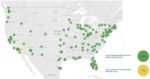
Throughout this time, the FAA has been diligently working with both the telecommunication companies and the aviation industry. Over 90% of the U.S. commercial aircraft fleet has been cleared for most low-visibility approaches in 5G deployment areas. Additionally, 99% of the affected airports have received approval for at least 90% of aircraft models to land in low-visibility approaches. Palm Springs International Airport is the only outlier with only 68% of aircraft models approved for low visibility approaches.

Figure 1: Map of U.S. airports detailing approved clearances for low visibility approaches

The FAA is pushing the airline industry to replace and retrofit the remaining 10% of radio altimeters that are at risk of interference from the C-Band 5G wireless service. This could require adding improved RF filtering to the radio altimeters or updating older altimeters to newer models which already have improved filtering and performance. The parties will take a phased approach with the hope of upgrading most aircraft by the end of 2022 and all aircraft by July 2023.

For additional background information, see Ansys’ earlier blog entries:

  1. 5G and Aircraft Safety: How Simulation Can Help to Ensure Passenger Safety
  2. 5G and Aircraft Safety Part 2: Simulating Altimeter Antenna Interference
  3. 5G and Aircraft Safety Part 3: How Simulation Can Validate Interference Scenarios

Future Considerations

While the parties have come together to avoid disaster, this instance highlights an ever-growing problem with potentially billions of dollars at stake in both the U.S. and internationally. There is already incredible demand for the limited spectrum and as the world becomes ever more connected, this demand will only increase. New sectors as wide ranging as industrial Internet of Things (IoT), private 5G networks, unmanned aerial vehicles, remote sensing, personal health networks and intelligent transportation systems will all compete for this limited resource with existing stakeholders such as the commercial aviation industry, maritime communications, TV broadcasting and more.

Some studies have found that use of spectrum in countries with advanced information and communication technologies has enabled an increase in GDP of 3.4%. Thus, it is imperative for stakeholders to ensure that they are efficiently using the spectrum allocated to them while also minimizing interactions with neighboring frequency bands. While EUROCONTROL found that the risk of 5G interference to radio altimeters in Europe was lower than that in the U.S., due to lower maximum power restrictions in Europe and an operating band (3.4-3.8 GHz) that is further from the radio altimeter band (4.2-4.4 GHz), it did find that the aviation industry does not make efficient use of its spectrum and can improve its process for developing new communication, navigation and surveillance (CNS) technologies.

A key recommendation of EUROCONTROL is to improve the adjacent band filtering. As the Radio Technical Committee for Aeronautics (RTCA) found, this poor adjacent band filtering had an outsized role in determining the performance of radio altimeters in the presence of 5G C-Band radios. Many of the altimeters in use today were developed decades ago, when the mid C-band frequencies were used for low power satellite applications which were a minimal risk to the altimeters.

Figure 2: “Assessment of C-Band Mobile Telecommunications Interference Impact on Low Range Radar Altimeter Operations”, RTCA Paper No 274-20/PMC-2073, from rtca.org. RTCA, Inc, Washington DC, USA

Long product cycles, 20-30 years for many aircraft, also makes it hard to perform CNS upgrades and the aviation industry should not skip incremental improvements while waiting for a dramatic leap in technology. Spectrum inefficiencies can be very costly in the long run and frequency congested systems can limit air traffic growth as we’ve seen with VHF COM in the past.

How Simulation Tools Could Help

These issues can be avoided with the help of simulation tools such as Ansys EMIT and the AGI System Toolkit (STK) which can predict and quantify these interference effects in dynamic scenes including flight paths and platform motion, and provide guidance for mitigation. Ansys AGI STK provides dynamic scene orchestration and platform motion physics for vehicles on land, air, sea and space, and is useful for considering flight paths and aircraft motion behavior impacts on sensor and antenna positioning during landing and takeoff sequences. The Ansys Electromagnetic Interference Toolkit (EMIT) is an integral component of the Ansys Electronics Desktop and part of the Ansys HFSS portfolio. EMIT is designed to consider wideband transmitter emissions and assess their impact on wideband receiver characteristics. Its detailed results analysis capabilities enable users to quickly determine design requirements for any adjacent band filters.

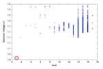
Let’s examine the results for the second phase of the C-Band service rollout in the 100 MHz band from 3.7-3.8 GHz. Figure 3 shows the result of our investigation. The black curve gives us a view of what is going on in the receiver and measures the difference between the transmitted power at each frequency and the receiver’s ability to reject that energy (receiver susceptibility). If this value goes above zero (shown by the red line), we have an interference event because the receiver can’t reject that level of energy at that frequency. We can also set threshold values to warn us if we are getting close to an interference event, such as the yellow line at -6 dB. This is important due to the dynamic environment that communications equipment is typically operated in. Aircraft takeoff and landing can be especially dynamic due to the low altitude and the higher probability of multipath from nearby buildings and ground reflections.

The plot in Figure 3 suggests that the 5G transmitter fundamental is strong enough to potentially saturate the front end of some radio altimeters. While this exact result is specific to the details of this simulation, to mitigate the risk, a bandpass or high pass filter could be added inline with the radio altimeter to better attenuate these near-band frequencies.

Figure 3: A high pass or band pass filter with at least 20 dB of attenuation would be required to prevent this 5G Radio from saturating the simulated radio altimeter

The filter can then be designed and synthesized using the Ansys Nuhertz FilterSolutions software and the results then added to your simulation to verify the performance and ensure that the interference was sufficiently mitigated.

Figure 4: Out-of-band performance of radio altimeter after adding an inline high pass filter with 30 dB attenuation

Simulation tools can also help regulating agencies with spectrum planning. This will be critical in the coming years as airlines look to increase capacity at existing airports, necessitating the need for more channels between the aircraft and air traffic control. Before additional frequencies can be assigned for use at an airport, it needs to be verified that they won’t interfere with and overlap with the bands used at other, nearby airports. As seen in Figure 6, EMIT’s Spectrum Utilization Toolkit enables users to quickly determine if a new allocation will overlap existing frequency bands.

Figure 4: Out-of-band performance of radio altimeter after adding an inline high pass filter with 30 dB attenuation

Frequency planning tools that are accurate, efficient and easy to use can assist regulators and the wireless telecommunications industry in allocating frequency spectrum. Systems operating in adjacent bands are easily identified, informing stakeholders of potential new sources of interference and enabling them to perform a more thorough analysis to determine if additional mitigation measures are required or quickly deciding that a particular allocation will not work as expected.

Also Read:

Ansys’ Emergence as a Tier 1 EDA Player— and What That Means for 3D-IC

What Quantum Means for Electronic Design Automation

The Lines Are Blurring Between System and Silicon. You’re Not Ready


WEBINAR: How to Accelerate Ansys RedHawk-SC in the Cloud

WEBINAR: How to Accelerate Ansys RedHawk-SC in the Cloud
by Daniel Nenni on 09-28-2022 at 8:00 am

How to Accelerate Ansys RedHawk SC in the Cloud


As we all know, growing complexity of IC designs and the resulting numbers of EDA tools and design steps lead to very intricate workflows which require compute cycles that outstrip current compute capacity of most IC enterprises. The obvious question is how to efficiently leverage near infinite compute capacity in the cloud without having to create a separate workflow. At the same time, we need to optimize the cost of cloud computing so that we can get the maximum number of compute cycles without incurring excessive data movement latency, application performance degradation or storage cost explosion overhead.

REGISTER HERE

To scale performance, most EDA tools have applied multi-core and multi-threaded execution techniques so that single job runs have use 100’s to 1000’s of CPU cores, which theoretically fits very well with the availability of core capacity in the cloud. The caveat is that many applications have chosen different and incompatible approaches to controlling and scaling multi-threaded jobs. Some use interprocess communication via TCP/IP messaging while others depend on shared file or database storage that all hosts access via NFS-like protocols.

Another facet of the challenge is identifying and transporting the input data (user workspaces, reference data like foundry kits and EDA applications) needed for these jobs in a time efficient manner. Since this data can run into the 100’s of TB, moving that data into a cloud environment can take weeks and synchronizing updates is likewise non trivial – especially of the goal is to support multiple on premise storage vendors and utilize multiple cloud vendors or regions.

From a practical standpoint, to get reasonable application performance in the cloud, the time invested in optimizing on premise storage infrastructure for cost & performance needs to be re-invested for cloud storage architectures, which can also vary from one cloud provider to the next.

So if we are going to efficiently use the cloud to augment our current infrastructure to meet the challenges presented by new technology nodes and EDA tools, we need to make sure to find solutions that:

-Minimize latency of getting data to and from the cloud so that we can actually increase throughput

-Use existing EDA workflows and tools out of the box so that we don’t have to rework or rearchitect to avoid engineering overhead costs that can run into the millions of dollars

-Maximize runtime performance so that we can run EDA applications faster in the cloud than on premise

-Eliminate the cost of duplicating all data in the cloud and having to incur the cost of keeping persistent copies in each cloud or cloud region we want to use

Our upcoming webinar for “How to Accelerate Ansys® RedHawk-SC™ in the Cloud” will show a practical solution that addresses all of the above challenges using the IC Manage Holodeck product. The webinar will show that Holodeck enables hybrid cloud bursting on Amazon AWS for Redhawk-SC and delivers:

-Low latency startup – less then 2 minutes to start a 2 hour Redhawk-SC job analyzing voltage drop and electromigration reliability in a massively complex power distribution network

-Identical Redhawk-SC setup and runtime settings as running on premise for the Ansys Galaxy 7nm design

-1.4X faster performance than using standard cloud NFS storage, even for a single compute node running the job

-80% storage reduction vs. copying all application and workspace data to the cloud

REGISTER HERE

Additional Info

IC Manage Holodeck is a 100% storage caching solution that enables EDA and HPC applications to run faster in the cloud and dramatically reduce cloud storage costs.

Ansys® RedHawk-SC™ is one of many EDA tools that runs on Holodeck and sees these benefits in running power integrity and reliability signoff for ICs by checking for voltage drop and electromigration reliability in massively complex power distribution networks.

Also read:

Effectively Managing Large IP Portfolios For Complex SoC Projects

CEO Interview: Dean Drako of IC Manage

Data Management for the Future of Design


Arm and Arteris Partner on Automotive

Arm and Arteris Partner on Automotive
by Bernard Murphy on 09-28-2022 at 6:00 am

Arteris Arm partnership

Whenever a new partnership is announced, the natural question is, “why?” What will this partnership make possible that wasn’t already possible with those two companies working independently? I talked yesterday with Frank Schirrmeister of Arteris on the partnership. (Yes, Frank is now at Arteris). And I just got off an Arm press briefing on their annual Neoverse update; not directly related to Arteris but heavily plugging the value and continued expansion of their ecosystem. The partnership is good for Arteris but also for Arm in continuing to widen the moat around their strategic advantages.

The first-order answer

Arm cores are everywhere: in mobile, in servers, in communication infrastructure and (most important here) in automotive applications. Arteris IP may not have the market presence of Arm but is also widely popular in automotive applications, including announced customers like BMW, Mobileye, Bosch, NXP, Renesas and many others. Both feeding solutions into an automotive ecosystem which continues to grow in complexity: OEMs, Tier 1s, Semis, IP suppliers, software vendors and cloud service providers. All supplying pieces like Lego® blocks which integrators expect to snap together seamlessly.

But of course, seamless fits between components from varied suppliers integrated into varied systems don’t just happen. Without collaborative partnering, integrators are left to bridge and force fit their own way through mismatches between multiple “almost compatible” components. Arm’s ecosystem, especially at the software level, is a great example of how to minimize integrator headaches in discovering and correcting such problems. The ecosystem assumes the burden of pre-qualifying and resolving integration issues. Integrators can focus instead on what will make their products compelling.

Arteris fits necessarily into the same objective. Optimally configuring the network-on-chip (NoC) bridging between most IPs in an SoC design is as critical to meeting design goals as selecting CPU and other cores. While many successful Arm- and Arteris-based designs are already in production, I’m sure there are areas where Arm and Arteris can work to provide a more seamless fit. Perhaps they can also provide added guidance to integrators. I’m guessing that a program in a similar general spirit to SystemReady® could help grade integrations against best practices.

My guess at a second-order answer

All goodness, but need the partnership stop there? I’m sure it won’t. Here again, I am speculating.

A logical next step would be more work on ASIL-D ready design support. This area has seen a lot of traction recently. An SoC incorporates a safety island, guaranteed ASIL-D ready and responsible for monitoring and reporting on the rest of the design. This communicates through the NoC, connecting to checkers at each network interface which test for consistency errors. A further level of sophistication allows IPs to be isolated on demand for in-flight testing. A failing IP could then be kept offline, signaling the need to report to the driver that a sub-system has a problem. While still allowing the rest of the system to function as intended. These capabilities are already supported in the Arteris IP FlexNoC Resilience package. I have no doubt a stronger integration with Arm-based safety islands could accelerate development of ASIL-D integrations.

Another area I see potential is in tighter integration with advanced AI accelerators. While Arm has its own AI solutions, the AI arena is fizzing with new accelerator options offering a wealth of differentiation. Building such accelerators and supporting their use in SoCs will be a fact of life for many years. Many accelerators use Arteris IP NoCs as their communication fabric. Because such architectures demand a high level of custom configurability, which these NoCs provide. Accelerators typically support AXI interfaces but also need coherence with the main compute pipeline. This is a capability Arteris can support through their Ncore coherent NoC.

Another obvious area for collaboration is in security. Arm is already a leader in this area with PSA and other standards. The NoC, mediating communication across the chip, must also work tightly with the security architecture.

This is good for automotive design

Both companies are well established and proven in automotive. I expect we will hear more over time about how they are expanding the value of the total solution. Good area to watch. You can read more HERE.


3D IC – Managing the System-level Netlist

3D IC – Managing the System-level Netlist
by Daniel Payne on 09-27-2022 at 10:00 am

2.5D IC min

I just did a Google search for “3D IC”, and was stunned to see it return a whopping 476,000 results. This topic is trending, because more companies are using advanced IC packaging to meet their requirements, and yet the engineers doing the 3D IC design have new challenges to overcome. One of those challenges is creating a system-level netlist so that 3D netlist verification tools can be run to ensure that there are no connectivity errors.

Here’s a cross-section of a 2.5D IC with chiplets containing multiple HBM and an SoC, using a silicon interposer with an organic substrate. Connectivity of this system could be captured in a Verilog netlist format, or even a CDL/SPICE format.

2.5D IC with memory and SoC

Stacking chips in 3D face-to-face is another advanced packaging method.

3D IC

Chip engineers and package engineers often use different tools and flows to solve issues like connectivity. Ideally, there would be a system-level connectivity flow that understands both the chip and package domains.

Siemens EDA is a vendor that has tools that span both realms of IC and packaging, and their connectivity product is called Xpedition Substrate Integrator (xSI). With the xSI tool an engineer can import multiple die, interposer, package and PCB abstracts, then build a system-level model of the connectivity. After a system-level netlist has been exported from xSI, it’s ready to be used by an LVS tool like Calibre.

Running Calibre in netlist versus netlist mode is a method to check that the system-level netlist from xSI matches each chip netlist. The xSI tool has a wizard GUI to help you create a Calibre 3DSTACK netlist and run control.

xSI wizard for netlist vs netlist

The Calibre runset takes care of netlist conversions, die name mapping between IC and package, and any desired Calibre options. A clean report means that xSI was used properly to build a system connectivity.

For 3D-IC designs the silicon interposer could be in CDL or Verilog format, but the organic substrate is designed by the packaging group using CSV or ODB++ format. Designers may need to short or open certain signals, but that would result in LVS comparison errors.

For a multi substrate 3D-IC design, using a silicon interposer plus organic substrate, the package team could user one name for a net, while the interposer team uses a different name for the same net. With xSI there’s a way to make this connection between two different net names, it’s called an interface part.

As an example, the following interposer has a net TEST_CLK, which is connected to the package substrate net pkg_TEST_CLK. The interface part allows these two differently name nets to be connected, and then running Calibre 3DSTACK will produce no false LVS errors.

Interface part in xSI

Sometimes in a 3D-IC assembly you need to short unneeded signals to ground, or even short two power planes together, but these nets are not connected in the system netlist. While creating the source netlist for Calibre 3DSTACK you can create a shorts list with the net mapping feature.

Summary

3D netlists present challenges to the IC and package design process, so Siemens EDA has come up with a tool flow using xSI and Calibre tools. Building the correct system-level netlist is validated by running a netlist vs netlist comparison. When you need to account for opens and shorts, then they can be waived by design. Even different net names between package and interposer design teams are supported with this flow of xSI and Calibre.

The complete nine-page white paper is online here.

Related Blogs


Arm 2022 Neoverse Update, Roadmap

Arm 2022 Neoverse Update, Roadmap
by Bernard Murphy on 09-27-2022 at 6:00 am

Neoverse update min

Arm recently provided their annual update on the Neoverse product line, targeting infrastructure from cloud to communication to the edge. Chris Bergey (SVP and GM for infrastructure) led the update, starting with a shock-and-awe pitch on Neoverse deployment. He played up that Arm-based servers are now in every major public cloud across the world. AWS of course, Google cloud, Microsoft Azure, Alibaba and Oracle all support Arm-based instances. In 5G RAN, Dell, Marvell, Qualcomm, Rakuten, HPE announced partnerships, joining Nokia, Lenovo, Samsung and more in this space. NVIDIA announced their Grace server CPU and HPE their ProLiant servers, also Arm-based. Like I said – shock and awe.

Perspectives from cloud builders, cloud developers

The cloud/datacenter backbone was at one time purely dependent on x86-based servers. Those servers continue to play an important role but now clouds must support a rapidly expanding diversity of workloads. CPU types have fragmented into x86-based versus Arm-based. GPUs are more common, for video processing support, gaming in the cloud and AI training. Specialized AI platforms have emerged like the Google TPUs. Warm storage depends on intelligent access to SSD, through Arm-based interfaces. Software defined networking interfaces are Arm-based. DPUs – data processing units – are a thing now, a descriptor for many of these data-centric processing units. Application-specific platforms for the datacenter, all of which are building on SystemReady® qualified Arm platforms.

Microsoft Azure made an important point, that the cloud game is now about total throughput at lowest operational cost, not just about highest performance. Power is a particularly important factor; even today power-related costs contribute as much as 40% of TCO in a datacenter. Mitigating this cost must touch all components within the center, compute instances, storage, AI, graphics, networking, everything. The Azure product VP stressed that Arm is working with them on a holistic view of TCO, helping them to define best solutions across the center. I assume Arm have similar programs with other cloud providers, shifting up to become a solutions partner to these hyperscalars.

Arm enables cloud independence

A developer advocate at Honeycomb (which builds an analysis tool for distributed services) made another interesting point: the ubiquity of Arm-based instances in the major clouds provides cloud independence for developers. Of course x86 platforms offer the same independence. I think the point here is that Arm has eliminated a negative through availability on a wide range of clouds.  Honeycomb also incidentally highlight the cost and sustainability advantages; Arm is calling this the carbon-intelligent cloud. Young development teams like both of course, but they also have an eye to likely growing advantages to their businesses in deploying on more sustainable platforms.

Product update

As a reminder the Neoverse family breaks down into three classes. The V-series offers highest performance per thread – the most important factor for scale-up workloads, such as scientific compute. The N-series is designed to provide highest performance per socket – the most important factor for scale-out workloads, good for (I’m guessing) massive MIMO basebands. The E-series is designed for efficient throughput in edge to cloud applications; think of a power over ethernet application for example.

The newest V-series platform is the V2, code-named Demeter. This offers improved integer performance, a private L2 cache to handle larger working datasets and expanded vector processing and ML capability. The platform now supports up to 512MB system level cache, a coherent mesh network with up to 4TB of throughput (!) and CXL for chiplet support. Supporting 2.5/3D coherent designs. Nvidia Grace is built on the V2 platform, which is interesting because Grace is one half of the Grace Hopper platform, in which Hopper is an advanced GPU.

In N-series, they plan an “N-series next” platform release next year with further improved performance per watt. They also have an E-series E2 update, and an “E-series-next” release planned next year. Not a lot of detail here.

About the competition

Seems clear to me that when Arm is thinking about competition these days, they are not looking over their shoulders (RISC-V). They are looking ahead at x86 platforms. For example, Arm compares performance on popular database applications between Graviton2 (AWS) and Xeon-based instances, measuring MongoDB running 117% faster than Intel. They also measured an 80% advantage over Intel in running BERT, a leading natural language processing platform.

I’m sure Arm is also taking steps to defend against other embedded platforms, but the Neoverse focus is clearly forward, not back. You can read more HERE.


UCIe Specification Streamlines Multi-Die System Design with Chiplets

UCIe Specification Streamlines Multi-Die System Design with Chiplets
by Dave Bursky on 09-26-2022 at 10:00 am

protocol stack 1

Over the last few years, the design of application-specific ICs as well as high-performance CPUs and other complex ICs has hit a proverbial wall. This wall is built from several issues: first, chip sizes have grown so large that they can fill the entire mask reticle and that could limit future growth. Second, the large chip size impacts the manufacturing yield, often causing diminishing returns (reduced manufacturing yields) for the large chips. Third, power consumption for the large monolithic chips has also reached critical levels and must be reduced to avoid thermal issues. And fourth, the need to mix different technologies with the advanced processes used for the digital core—non-volatile memories, analog and RF functions, high voltage drivers, and high-speed serial interfaces—can limit what designers can integrate on a single chip due to process incompatibilities.

To deal with these challenges, designers have started to disaggregate their chip designs by splitting the large chips into smaller dies that are now referred to as chiplets. However, therein resides another problem – the lack of standardization regarding chiplet sizes, interfaces, and communication protocols. That, in turn, limits design flexibility and the ability to mix and match chiplets from multiple suppliers. Trying to solve some of those issues, the recently introduced Universal Chiplet Interconnect Express (UCIe) specification goes a long way towards easing the designer’s job of crafting customizable package-level integration of multi-die systems explains Manuel Mota, Product Marketing Manager in the Synopsys Solutions Group. It has the support to make the marketplace for disaggregated dies truly vibrant—one with plug-and-play-like flexibility and interoperability.

Mota expects that the specification will help establish a robust ecosystem for a new era of SoC innovation. In addition to supporting different chiplets fabricated on different process nodes that are each optimized for each particular function, a multi-die architecture also allows integration of dies from digital, analog, or high-frequency processes. Designers can also incorporate three-dimensional high-density memory arrays, such as high-bandwidth memory (HBM) chip stacks into the 2D, 2.5D, or 3D packaging configurations.

Although the UCIe specification is fairly new, there have been several different standards prior to UCIe that address the challenges of multi-die systems, but mostly from the physical design aspects of multi-die system design. The OIF Extra Short Reach (XSR), Open Compute Project Bunch of Wires (BOW) and OpenHBI (OHBI), and Chip Alliance Advanced Interface Bus (AIB) are the alliances and standards for 2D and 2.5D package types. These standards provide bandwidth versus power tradeoffs with a primary focus on providing transport connectivity between chiplets.

UCIe is the only specification that defines a complete stack for the die-to-die interface. The other standards focus only on specific layers and, unlike UCIe, do not offer a comprehensive specification for the complete die-to-die interface for the protocol stack. As Mota explains, Synopsys looks forward to our future contributions to the UCIe specification. Along with the promoting members AMD, Arm, ASE Alibaba, Group, Google Cloud, Intel, Meta, Microsoft, NVIDIA, Qualcomm, Samsung, and TSMC, we are looking to actively help promote a healthy ecosystem for UCIe.

Not only does UCIe accommodate the bulk of designs today from 8 Gbps to 16 Gbps per pin but it also accommodates designs at 32 Gbps per pin for high-bandwidth applications from networking to hyperscale data centers. UCIe is comprised of two package variants: UCIe for advanced packages, such as silicon interposer, silicon bridge, or redistribution layer (RDL) fanout; and UCIe for standard packages, such as organic substrate or laminate.

The UCIe stack consists of three layers. The top Protocol Layer ensures maximum efficiency and reduced latency through flow-control-unit-based (FLIT-based) protocol implementation, supporting the most popular protocols, including PCI Express® (PCIe®), Compute Express Link (CXL), and/or user-defined streaming protocols. The second layer is where the protocols are arbitrated and negotiated and where the link management occurs through a die-to-die adapter. The third layer, the PHY, specifies the electrical interface with the package media. This is where the electrical analog front end (AFE), transmitter and receiver, and sideband channel allow parameter exchange and negotiation between two dies. Logic PHY implements the link initialization, training and calibration algorithms, and test-and-repair functionality (see the figure).

Whether the primary goal is high-energy efficiency, high-edge usage efficiency, low latency, or all of the above, the UCIe specification has very competitive performance targets. To help you in your journey of adoption, Synopsys offers a complete UCIe Solution, allowing designers to put the specification into practice with PHY, controller, and verification IP (VIP).

The PHY interface supports both standard and advanced packaging options and is available in advanced FinFET processes for high-bandwidth, low-power, and low-latency die-to-die connectivity. The controller IP supports PCIe, CXL, and other widely used protocols for latency-optimized network-on-chip (NoC)-to NoC links with streaming protocols; for example, bridging to CXS interfaces and to AXI interfaces. Lastly, the Synopsys Verification IP (VIP) for UCIe supports various designs under test (DUT) at each layer of the full stack. The VIP includes testbench interfaces with/without PCIe/CXL protocol stack, Application Programming Interface (API) for sideband service requests, and API for traffic generation. Protocol checks and functional coverage are at each stack layer and signaling interface. It enables scalable architecture and Synopsys-defined interoperability test suites.

The Synopsys solution enables robust and reliable die-to-die links with testability features for known good dies and CRC or parity checks for error correction. It enables designers to build seamless interconnects between dies for the lowest latency and highest energy efficiency. With multi-die system designs, an increase in payloads due to multiple streaming protocols could take days or even months for simulations, limiting its usefulness.

To verify a multi-die system, designers can first create various single-node and multi-node models, simulating these minimalistic systems to check the integrity of data. Once those scenarios are tested, designers can then test in higher-level system scenarios with multi-protocol layers using the Synopsys ZeBu® emulation system, and then move to prototyping with the Synopsys HAPS® prototyping system. This flow from models to simulation to emulation to prototyping, using our verification IP and other protocol verification solutions, will help you ensure seamless interoperability pre-silicon.

Multi-die system design is a great option to catapult systems beyond the limitations of Moore’s law. With it, designers can realize new levels of efficiencies and performance while reducing power and area footprints. UCIe is helping to fast track this new way of designing for advanced applications. To learn more about how UCIe facilitates multi-die system designs, check out the Synopsys article, Multi-Die SoCs Gaining Strength with Introduction of UCIe.

For a list of UCIe compatible verification IP products, go to https://www.synopsys.com/verification/verification-ip.html, and for UCIe IP, go to https://www.synopsys.com/dw/ipdir.php?ds=dwc_ucie_ip.

Also Read:

Methodology to Minimize the Impact of Duty Cycle Distortion in Clock Distribution Networks

Methodology to Minimize the Impact of Duty Cycle Distortion in Clock Distribution Networks
by Kalar Rajendiran on 09-26-2022 at 6:00 am

Figure Gate Failing to Reach 1.1V

Synchronous circuits dominate the electronic world because clocking eases the design of circuits compared to asynchronous circuits. At the same time, clocking also introduces its share of challenges to overcome. No wonder, a tremendous amount of time and effort have been spent over the years on developing and implementing various types of clock distribution networks. A lot of time has also been spent on analyzing and addressing clock jitter due to power supply. And at the design level, a lot of thought goes into choosing the clock duty cycle when designing a circuit.

In terms of accuracy, SPICE simulations have always been held as the gold standard. But SPICE simulations are compute-time intensive and typically run on just small portions of a design.  Instead, gate level simulation was used as the default signoff tool for chips until the turn of the 21st century. This worked well as most of the designs then were not very large or complex and the process nodes in use were 250nm or larger. As process nodes advanced and design size and complexity started growing, gate level simulation as a signoff tool started getting strained. Static timing analysis (STA) took over as the default signoff tool and has worked well for the last two decades. But today’s advanced-process-based designs are facing chip-signoff challenges due to limitations of STA and duty cycle distortions (DCD). While the intrinsic limitations of STA were always present, they did not pose practical issues when it came to signoff on less advanced process nodes. And while duty cycle distortions go hand in hand with clocking, they were either corrected with a DCD correcting circuit or were not serious enough to impact the proper functioning of a design. But no longer.

We’re entering an era where STA needs to be augmented for addressing DCD and increasing verification coverage for high confidence at chip signoff. Wouldn’t it be great if overnight simulation runs on multi-millions of gates can deliver SPICE level accurate results? Infinisim has published a whitepaper that explains how their analysis tools and methodology can deliver all of the above. This blog covers the salient points from that whitepaper.

Duty Cycle Distortion (DCD)

Duty cycle distortion (DCD) is a propagation delay difference between low-to-high and high-to-low transitions of the clock and is typically expressed in percent. With 7nm and below, deep clock distributions are prone to DCD accumulation as the signal propagates through different levels. With millions of gates on a single clock domain, even a picosecond DCD per gate will add up to significant distortions at the end points. While DCD results from manufacturing process variations, marginal designs and electrical noise, it gets worse with transistor aging. Traditionally, duty cycle correcting circuits have been added to designs to remedy the problem.

Duty Cycle Correcting Circuit

Duty cycle corrector circuits work by adding or removing delay from the rising or falling transition until an expected duty cycle is reached. While duty cycle corrector circuits may help reduce DCD, they add complexity to the clock design of today’s already complex chip designs. With time to market pressure ever increasing, the goal is to reduce complexity wherever one can in order to get the chip out on schedule. Implementing a methodology that accurately analyzes DCD can eliminate the need for DCD correcting circuit and reduce the complexity of a design.

Limitations of STA

STA tools do not compute the full clock signal waveforms. Instead,  they estimate timing values by inferring them from pre-characterized timing libraries for different PVT corners. While this makes STA fast, it is not accurate enough at finer geometries, failing to detect DCD and rail-to-rail failures directly.

At sub 7nm designs with higher transistor nonlinear effects, increased aging and deep clock distributions, complex analysis is not possible with traditional STA. In addition, STA is especially inaccurate for advanced clock topologies containing meshes and spines. In essence, DCD, rail-to-rail and minimum clock pulse width problems are critical issues that can go unnoticed during STA, resulting in serious failures in silicon.

Infinisim’s ClockEdge

Infinisim’s ClockEdge is a high-capacity, high-performance, SPICE accurate, end-to-end integrated clock analysis solution. ClockEdge can handle chips that incorporate multiple topology high-speed clocks and used for full-chip sign-off. It plugs into current design flows, allowing designers to simulate large clock domains with millions of gates.

Overnight Runs on the Gold Standard

Infinisim’s ClockEdge computes DCD using SPICE simulations of an entire circuit using full interconnect parasitics. The simulator identifies the nets that are failing duty cycle, minimum pulse width and rail-to-rail failures. It generates clock waveforms and estimates the maximum frequency at which rail-to-rail failures occur. SPICE accurate results are delivered overnight on clock domains containing 4+ millions gates, which is unheard of in standard SPICE simulations.

High Verification Coverage

Designers can run multiple PVT corners and input duty cycles for comprehensive and increased design verification coverage thereby gaining high confidence in their design. ClockEdge users routinely find DCD issues missed by STA-based-CTS methodologies.

Some Salient Features of ClockEdge

    • SPICE accurate results overnight, for clock domains containing 4+ million gates
    • Leverages distributed computing to simulate and analyze large complex clocks
    • Handles complex clock topologies includes trees, grids/mesh and spines
    • Reports include timing, process variation, power and current analysis
    • OCV analysis: during design for guard-band reduction, in post-design phase to estimate yield
    • Results from ClockEdge are integrated into CTS flow for optimizing design

Some use cases below where ClockEdge augments STA for SPICE accurate, comprehensive timing analysis:

    • Timing optimization during design iterations
    • Base-layer tapeout/Metal-layer tapeout signoff verification
    • Post-fab investigation into performance degradation and potential improvements for next revision

Rail-to-Rail Failures Report

ClockEdge also reports rail-to-rail failures by plotting the maximum and minimum voltages reached by every node in a full clock domain. The Figure below shows ClockEdge identifying a gate at level 1 failing to reach supply voltage of 1.1v.

Fmax Report

The data can also be represented in a Fmax plot to show the expected maximum frequency (Fmax) at which rail-to-rail failures would occur for each node. Refer to the Figure below.

The above reporting capability allows designers to quickly determine if there are any rail-to-rail failures amongst the millions of nodes on a particular clock path.

Summary

ClockEdge delivers SPICE accurate results on clock domains containing 4+ millions gates and higher verification coverage compared to competitive products in the market. It easily plugs into current design flows used by customers. And it can accurately analyze top-level, block-level and hard-macro level clocks to cover all blind spots. The tool finds DCD, jitter, aging and rail to rail issues that are routinely missed by traditional STA-based methodologies.

For more details about ClockEdge, you can access the whitepaper here.

To learn about a comprehensive solution for full-chip clock analysis, visit Infinisim.

Also Read:

WEBINAR: Challenges in analyzing High Performance clocks at 7nm and below process nodes

WEBINAR: Overcome Aging Issues in Clocks at Sub-10nm Designs

White Paper: A Closer Look at Aging on Clock Networks


Podcast EP108: Brief History of the Semiconductor Industry – How Did It Get Started?

Podcast EP108: Brief History of the Semiconductor Industry – How Did It Get Started?
by Daniel Nenni on 09-23-2022 at 10:05 am

Dan is joined by Chris Miller, Associate Professor of International History at The Fletcher School and author of Chip War: The Fight for the World’s Most Critical Technology, a geopolitical history of the computer chip. Chris provides a far-reaching overview of the forces that shaped the worldwide semiconductor industry, with a special view of the R&D done by US aerospace and defense in the early days. The forward-looking strategies that were developed are truly remarkable.

The views, thoughts, and opinions expressed in these podcasts belong solely to the speaker, and not to the speaker’s employer, organization, committee or any other group or individual.


Semifore is Supplying Pain Relief for Some World-Changing Applications

Semifore is Supplying Pain Relief for Some World-Changing Applications
by Mike Gianfagna on 09-23-2022 at 8:00 am

Semifore is Supplying Pain Relief for Some World Changing Applications

In a recent post, I discussed how Samtec is fueling the AI revolution. In that post, I talked about how smart everything seems to be everywhere, changing the way we work, the way we think about our health and ultimately improving life on the planet. These are lofty statements, but the evidence is growing that the newest wave of applications could do just that. If you take a closer look at the technology that is enabling all this, you will find two primary drivers – better/faster AI and more ubiquitous and efficient data communication. Semifore has recently issued two press announcements about new customers in AI and data communication. Let’s look at those announcements. I believe you will see a pattern – Semifore is supplying pain relief for some world-changing applications.

Data Communication

The first press announcement is about CommScope. In that announcement it is reported that CommScope will expand the term of its use of Semifore solutions for the design of advanced communication devices through a multi-year agreement.

Who is CommScope and how is this relevant? According to its website:

At CommScope we push the boundaries of communications technology to create the world’s most advanced networks. We design, manufacture, install and support the hardware infrastructure and software intelligence that enable our digital society to interact and thrive. Working with customers, we advance broadband, enterprise and wireless networks to power progress and create lasting connections. Across the globe, our people and solutions are redefining connectivity, solving today’s challenges and driving the innovation that will meet the needs of what’s next.

This is the kind of holistic approach that’s needed to truly unify communications on a global scale. It goes toward the goal of changing the world by unifying the data in the world. Building systems like this isn’t easy. There are many, many hurdles to cross. These systems contain large amounts of hardware as well as massive software stacks. Getting the interaction between the hardware and software right is one of those hurdles.

Here is where Semifore provides pain relief. CSRs, or control status registers is where the interface between software and the hardware it controls occurs. These registers define the communication protocol between hardware and software and the correctness of that interface is absolutely critical to success.  According to CommScope:

“We have used other CSR EDA tools over the years, but Semifore’s CSRCompiler offers the fullest featured and most flexible tools as well as easiest to use,” said Andy Mansen, senior manager of hardware engineering at CommScope. “It eliminates all confusion around CSR.”

Semifore to the rescue.

AI Acceleration

The second press announcement is about Flex Logix. In that announcement it is reported that Flex Logix selects Semifore for advanced inference chip design.

Inference is the process AI uses to recognize things – people in front of a car, spoken language, or cancer cells for example. These systems demand very fast response time with very low latency. You do want to recognize a pedestrian in front of your self-driving car long before you hit the person for example. As a result of demands like this, more and more AI processing is moving from the cloud to the edge, or even onto the sensing device itself. There just isn’t time to do it any other way.

This trend, in turn, has created a rather vexing problem. How do you fit all that processing power in the rather small space and energy budget available? It is here that Flex Logix delivers innovation. According to Flex Logix:

Flex Logix is a reconfigurable computing company providing AI inference and eFPGA solutions based on software, systems and silicon. Its InferX™ X1 is the industry’s most-efficient AI edge inference accelerator that will bring AI to the masses in high-volume applications by providing much higher inference throughput.

So, help is on the way for local, efficient inference. You can learn more about Flex Logix on SemiWiki. But, just as with data communication, there is a catch. These are very complex devices, and the hardware/software interface is a challenge. According to Flex Logix:

“We are redefining the deployment of inference at the edge with our highly efficient technology,” said Charlie Roth, VP of Hardware R&D at Flex Logix. “These designs are highly complex, and the hardware and software interfaces are critical to performance and core functionality.  Semifore’s CSRCompiler ensures the hardware and software interfaces function as expected, and that both the hardware and software teams can test interaction during chip development.”

Once again, Semifore to the rescue.

More About Semifore

I caught up with Semifore’s founder and CEO, Rich Weber recently. A lot of the support for specification of the hardware/software interface is provided by industry standards. I wanted to see if Semifore was following that work. What I discovered is that not only is Semifore following relevant standards, but their team is driving and defining many of them.

Rich told me that he personally has been a voting member of the Accellera SystemRDL 1.0 and 2.0 committees, the IEEE 1685 2009 and 2014 committees and the Accellera UVM committee. Rich is also co-chair of the Accellera IP-XACT 1.5, 2.0, and 2.1 committees and he is currently the secretary of the IEEE 1685 2022 committee. Busy guy.

He also told me that Jamsheed Agahi, a Semifore co-founder and VP of quality is the secretary of the Accellera UVM committee, has been the secretary of the IEEE 1800.1 UVM committee and is a voting member of the Accellera Portable Stimulus committee.

These two gentlemen are driving important work for system design.

Are you working on a project that aims to change the world? If so, you are likely to encounter many hurdles with lots of pain. The good news is that help is available for some of that pain. You can learn more about Semifore’s pain-relieving products on SemiWiki here.  There is a lot of good information on Semifore’s website as well.  There’s also a webinar coming up that provides a clever perspective on how the RTL architect, verification engineer and firmware developer try to work together on complex, world-changing projects.

Now you know how Semifore is supplying pain relief for some world-changing applications.


Enjoy the Super-Cycle it’ll Crash in 2023!

Enjoy the Super-Cycle it’ll Crash in 2023!
by Malcolm Penn on 09-23-2022 at 6:00 am

Semiconductor Crash 2022

At our January 2021 industry update webinar, 20 months ago, we forecast “There’s no tight capacity relief before 2022 at the earliest” whilst simultaneously cautioning “Enjoy the super-cycle … it’ll crash in 2023!”  At the time, we were dismissed as being ‘ever optimistic’ for the first prognosis and ‘losing the plot’ for the second. 20 months down the road, both predictions have transpired to have been astutely prescient.

We made those predictions based on our tried and tested methodology of analyzing what we see as the four key driving factors influencing market growth, namely the economy, unit demand, capacity and ASPs, overseen by our 55 years of hands-on experience in the industry.

Just to recap, the economy determines what users can afford to buy; unit demand reflects what users actually buy; capacity determines how much demand can be met; and ASPs set the price units can be sold for.

Industry Update

Twelve months later, at our Jan 2022 update webinar, we forecast 10 percent growth was still possible for 2022, but with a downside of 4 percent and upside of just 14 percent.  Our concerns at that time were that the risks outweighed the opportunities; the chip market was seriously overheating; and the road ahead very stony.  We were especially worried about:

  • Supply/Demand Rebalance (Once The 2021 CapEx Increases Bite Home)
  • Slowdown In End Demand (Covid Surge Slowdown and/or Supply Chain Constraints)
  • Economic Slowdown (Covid Restrictions, Inflation Concerns, Unwinding Fiscal Stimuli)

Our over-riding caveat was “When the bubble bursts, it burst, there are no soft landings”.  First unit shipments plummet and then ASPs collapse, with the added word of caution “Don’t be surprised if the market goes negative … it more often does than not.”

Five months later, at our May update event, despite most firms still reporting stellar first half year sales, we were once again out on a limb, reducing our January 10 percent forecast to just 6 percent, due to concerns about the worsening economic outlook, driven by increased food, energy and gasoline costs wrought by Russia’s war with Ukraine, and its squeeze on consumer spending.  At that time, we reiterated our belief that the downturn would hit in Q3, triggered by the anticipated capacity increases loosening up supply constraints.

The downturn actually broke in June 2022, with a huge implosion in sales driven by a slowdown in unit shipments and an 18 percent fall in ASPs, from Q2’s $1.350 peak to $1.105, wiping out in one month 77 percent of the Super-Cycle’s gain. This pushed our January and May forecasts well into bear territory.

Granted downturns are always uneven and patchy at the start, partly driven by their commodity nature, or not, and partly because there is at least four months’ of WIP production in the wafer fab pipeline which cannot be stopped, but we firmly believe no sector will prove 100 percent immune. As we move towards 2023, the inflation outlook is much worse than we originally believed, in the high double-digit range, with the Fed now having abandoned its ‘soft landing’ goal. Interest rates everywhere, except China, are now poised to rise much faster in response, despite the obvious and clear risk of triggering an economic recession.

At the same time, Russia has now openly declared weaponization of its oil, natural gas, and mineral supplies, especially In Europe, and China’s still aggressive Covid zero tolerance strategy continues to disrupt the global supply chains everywhere. War sanctions on Russia are inevitably also disrupting the global economy and heightened geopolitical tensions with China re Taiwan and the US technology sanctions are also raising the global tension thermometer.

Current Status

As we entered the third quarter, the chip industry is facing a simultaneous series of global economic shocks coincident with slowdown in market demand. Every single warning light on the economy is now flashing red. Unit shipments are still running about 20 percent above their long-term average and a sharp downward adjustment is inevitable as lead times start to shorten and excess inventory is purged.

CapEx spend, as percentage of semiconductor sales, is at 20-year record high, with the massive 2H-2021 74 percent increased CapEx splurge about to hit home in 2H-2022, just as the market demand turns down. The current ASPs plunge has been driven by memory, but all other sectors are weakening and expected to follow suit in 1H-2023.

We reached the top of the semiconductor Super-Cycle roller-coaster in Q2-2022 and the downward plunge started in June. Sectors in the front are already feeling the impact; for those in the rear? Their start has yet to come. The 17th industry down cycle has now definitely begun.

We have revised our 2022 forecast down to 4 percent growth, but held our 2023 outlook at a 22 percent decline, back to around US$450 billion, and, all things being equal, we should be back to single-digit positive growth in 2024.

Downturn Opportunities

Downturns are a structural part of the industry psyche, which is quite natural and normal. They are also a time when longer-term market share gains are best made.

It is also a time when innovation comes to the fore. Firms need to emphasize new products to differentiated from their competitors and invent their way out of the crisis.

Innovation tends to slow during an upturn as foundries and IDMs ration R&D access to scarce wafer fab capacity. The opposite happens in a downturn when fab capacity becomes abundant.

As a result, R&D and new IC design activity always accelerates during a downturn and, as with the past cycles, the downturn beneficiaries will be the IC design houses, EDA industry and leading-edge suppliers.

Malcolm Penn

20 Sep 2022

Preview of the webinar proceedings here: https://youtu.be/PX9TmRTzD18

Order the webinar slides and recording here: https://www.futurehorizons.com/page/133/

Also Read:

Semiconductor Decline in 2023

Does SMIC have 7nm and if so, what does it mean

Samtec is Fueling the AI Revolution