The core of the technical program consists of 163 peer-reviewed papers with 35% of the content on ESS and 65% on EDA. Papers were selected from 742 submissions, the highest number of submissions to the conference in the past 5 years, and increase of 7% from 2011. Organized in the 35 technical paper sessions, these papers cover a broad set of topics ranging from system-level design, low power, physical design and manufacturing, embedded systems and software, logic and high level synthesis, simulation, verification, test and emerging technologies. Popular submission themes were:
Emerging Technologies
The submissions reflect that DAC has become the central conference to showcase tools and methodologies for traditional EDA design, Embedded Systems, and for Emerging Technologies.
The technical program committee’s excitement about the technical content is reflected in the session titles, “Yin and Yang of Memories: the power-performance trade-off”, “Routing Rules!”, “Yielding in an Uncertain World”, “Why Model? Because reality is complicated enough!”, “Staying cool: modeling thermal effects in 3D and multi-core”, “Top Picks of Run-Time Power Management Techniques”, “SOS: Specification, Optimization and Synthesis in System-Level Design”, and “Design Automation for Things Wet, Small and Spooky”.
SPECIAL SESSIONS:
10 special sessions will deal with a wide variety of themes from physical design to embedded software, including progress in design closure, power at different levels of abstraction, heterogeneous platforms, probabilistic embedded computing, self-aware and Adaptive Technologies and neuromorphic computing.
This year special sessions will also focus on how EDA can be applied to non classical EDA applications and problems such as the electronic counterfeit, wireless sensor networks design, medical devices designs.
USER TRACK: (sponsored by Apache Design, an ANSYS subsidiary)
The User Track highlights contributions by users of EDA and Embedded Systems tools and flows, targeting designers and practitioners: design tool users, hardware or software designers, application engineers, consultants, and flow or methodology developers.
We have some exciting changes for the User Track this year. The Tuesday and Wednesday sessions will take place adjacent to the exhibit floor. In addition, one of the DAC keynotes is dedicated to the User Track this year. We have invited the project managers of two industry-leading chips to discuss their designs and associated design challenges. Both managers will bring some senior members of their staff for an interactive panel-Q/A session to be held the same day as their keynote.
This year, we received 142 submissions, with authors from 90 institutions! The reviewing committee consisted of 35 industry experts representing user communities at 24 different companies. The User Track program includes the keynote, 8 paper sessions, 2 poster sessions, and the design panel session. The topics span embedded software to lithography and highlight challenges, solutions and methodologies covering verification, timing analysis, ASIC and FPGA design flows, IP block integration, test and debug.
PANELS:
For DAC 2012, a pervasive theme that panels address is: Have we reached a tipping point for a variety of technologies? High-level synthesis, system models, 3D chips, FPGA expansion, parallel EDA, and the cloud are technologies that have been discussed and researched for some time now; this year we separate the reality from the anticipation. Many DAC 2012 panels discuss whether each of these technologies is about to tip, taking off to become mainstream and thereby changing the face of the EDA industry. In addition, other panels address vexing issues like the impact of reliability, low-power design and automation, and the role of software versus hardware
TUTORIALS:
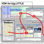
As in the past, the goal of the DAC tutorials is to provide practical, useable, and up-to-date knowledge that attendees can immediately apply in their jobs or studies. This year’s program includes six tutorials on timely subjects, including three system level topics – virtual platforms, system level power modeling, and high level synthesis; and three design topics – addressing 20nm design challenges, implications of 3DIC and Wide I/O on Design, and Analog / Mixed signal at advance process nodes.
EXHIBIT FLOOR
With over 200 exhibitors, including 21 first time exhibitors, this year’s exhibit floor offers exciting technologies and vendors to DAC attendees. New this year is the ARM Connected Community Pavilion, where attendees can visit ARM technology based demos from ARM partners. The exhibits are open Monday, Tuesday and Wednesday with the User Track presentations on Tuesday and Wednesday.
EMBEDDED SYSTEMS & SOFTWARE (ESS) Executive Day 2012 (Wednesday, June 6)
The ESS Executive Day is a day-long track of sessions dedicated to bringing industry stakeholders together in one room to shed light on where system design is headed. The day is comprised of presentations from leading industry executives representing the embedded development ecosystem. IC design engineers, embedded systems designers, embedded software and hardware IP providers, IP integrators, FPGA designers, investors, foundry reps, and the media will be on hand in this new forum to hear from market leaders and to network with each other.
Presenters will focus on optimization of embedded and application-domain specific operating systems, system architecture for future embedded products, application-specific architectures based on embedded processors and technical/business decision making by program developers. They will cover the state-of-the-art solutions for embedded software and systems and complex chips. Such solutions often require tight collaboration between diverse players in this ecosystem. Moving to new levels of complexity can significantly affect the choices of suppliers. The new ESS Executive Day provides a unique opportunity to foster discussions that address all aspects of the embedded development ecosystem
Management Day 2012 (Tuesday, June 5)
The rubber meets the road at the intersection of low power Systems-on-Chip design and the adoption of emerging technologies. Management Day at the 49[SUP]th[/SUP] Design Automation Conference (DAC) provides engineering and business managers with essential information to make the right decisions at the intersection of business and technology.
“Optimizing for volume production, low power, and shrinking sizes necessitates accurate trade-off analysis to drive technical/business decision-making,” said Yervant Zorian, 49[SUP]th[/SUP] DAC Vice Chair and Management Day Coordinator. “Moving to new semiconductor technology nodes such as 20nm can significantly affect the choices of suppliers. The Management Day sessions were designed to create lively dialog and to provide decision criteria to guide managers towards optimum choices from a pool of alternative options for flows, methodologies and suppliers.”
Management Day at DAC 2012 will feature presentations by managers from independent device manufacturers (IDMs), fab-light ASIC providers, foundries, and fabless companies. Senior managers of today’s most complex nanometer SoCs will discuss the latest emerging solutions, along with their economic impact. A third panel session will involve the audience in an open brainstorming discussion and will complement the presentation sessions.