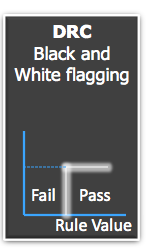

Last week GLOBALFOUNDRIES and Mentor Graphics presented at the Tech Design Forum on how they collaborated on a third generation DFM flow. When I reviewed the slides of the presentation it really struck me on how the old thinking in DRC (Design Rule Checking) of Pass/Fail for layout rules had been replaced with a score represented as a number between 0 and 1.

An example is shown above where an enclosure rule is described as:M1 minimum overlap past CA for at least two opposite sides with the other two sides >= 0.00um (Rectangular enclosure).
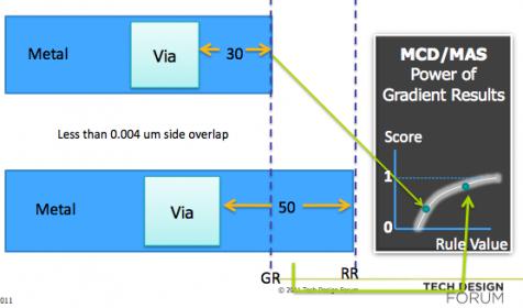
The top Metal line has a Via with short overlap and its score is about 0.4 (less manufacturable, lower yielding) while the bottom Metal line has a Via with a much longer overlap so its score is about 0.9 (more manufacturable, higher yielding).
When I first started designing full-custom ICs all of our rules were described as Pass/Fail, nothing ambiguous at all. Today however DRC rules are a different story at the 28nm node and lower because of DFM and lithography challenges, so IC designers need a new way to be warned about layout practices that impact yield early in the design process.
One way that GLOBALFOUNDRIES started describing the scoring on a rule was to provide two categories of rules: Low Priority and High Priority
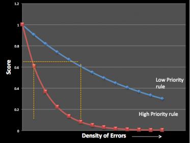
MCD Scoring Model
The blue line on the top is for Low Priority rules and the X axis represents the Score, while the slope of the line gradually moves downward. In contrast the High Priority rule line shown in red has a much steeper slope, meaning that it’s score approaches Zero more quickly.
With just these two rule lines we can bound all of the DRC rules in our process by placing each rule into one of two categories: High or Low priority.
An improvement over the MCD scoring model is called the MAS scoring model where each DRC rule has its own slope based on actual Silicon measurements:
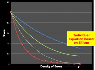
MAS Scoring Model
The green and grey lines correspond with two DRC rules that have been measured and plotted.
This new MAS Scoring Model is support by Mentor’s Calibre CFA tool:
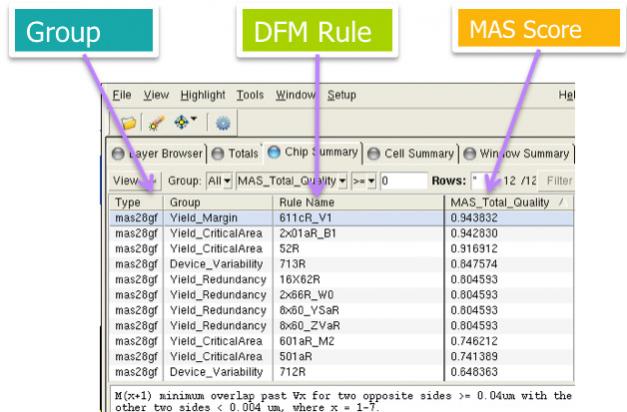
In this dialog I can see the MAS score for each DFM rule and then decide if I want to edit my layout to improve the score.
Many process effects are covered by the MAS score: litho, stress, charging, random particle defect, etc.
I can now sort and rank which DFM layout issues to work on first.
Summary
GLOBALFOUNDRIES is using DFM scoring to qualify IP at the 65nm and smaller nodes as a means to improve quality. Mentor Calibre tools use the equation-based MAS and litho friendly design so that a designer can converge more quickly on DFM fixes in their IP.


TSMC CoPoS Versus Intel EMIB Semiconductor Packaging