

The stochastic nature of imaging has received a great deal of attention in the area of EUV lithography. The density of EUV photons reaching the wafer is low enough [1] that the natural variation in the number of photons arriving at a given location can give rise to a relatively large standard deviation.
In recent studies [2,3], it was shown that large 2D complex patterns with a large diffraction spectrum can divide a large number of photons into smaller groups, each representing a different interference pattern. Each group therefore has a relatively more significant shot noise. However, the effect of defocus had not yet been considered.
In this article, it will be shown that even for a single photon group for a basic 2-beam interference pattern, when a large number of source points are used, the effect of defocus is to, once again, divide the total number of photons into smaller groups, each representing a different degree of defocus, as determined by the phase difference between the two interfering beams, referred to as the 0th and 1st diffraction orders. This, in turn, causes a more rapid degradation of the image.
Separation of Source Points by Defocus
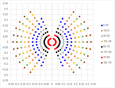
Figure 1 shows all the possible source points that can contribute to imaging a 40 nm line pitch, under the condition of 60 nm defocus. The source point coordinates are the sines of the angles with respect to the optical axis. At the nominal EUV wavelength of 13.5 nm and numerical aperture of 0.33, the 40 nm pitch can only be imaged as a 2-beam interference. Moreover, some source points (not shown) cannot provide an interference pattern, only background light.

Figure 1. Source points for two-beam interference at 40 nm pitch, classified by the phase difference between the interfering beams at 60 nm defocus (wavelength = 13.5 nm). The phase difference from 60 nm defocus is calculated by 360 deg/13.5 nm * 60 nm * [cos(0th order angle) – cos(1st order angle)].
Figure 1 shows only those points producing 2-beam interference, categorized according to phase difference between the interfering 0th and 1st orders. From the image differences among the groups in Figure 2, we can roughly divide the photons by defocus into 0-30 deg, 30-50 deg, 50-70 deg, 70-90 deg, in both positive and negative directions, leading to eight groups total, with the photons roughly uniformly distributed among them.

Figure 2. Effect of defocus phase difference between 0th and 1st orders on the image.
With significantly fewer photons per phase difference range, the stochastic impact is aggravated. The degree of defocus of the wafer image becomes effectively determined by the variable number of photons per phase difference range.
Phase defect sensitivity
EUV masks are also subject to phase defects, which can be manifest as sub-nm height bumps [4]. These phase defects change the vertical location of best focus and introduce small CD errors. The stochastic impact will manifest itself as defocus variation, i.e., how far the wafer location is from best focus, as well as CD variation (see Figure 3).

Figure 3. A phase defect combined with defocus lead to a more severe CD error. This is for the two-beam interference case as in Figure 1. A 30 degree defocus-induced phase difference between 0th and 1st orders is assumed. A 20 deg 10 nm wide phase line defect in a nominal 20 nm wide exposed line region (40 nm pitch) is also assumed.
Remaining Concerns for Using Low Pupil Fill
The impact of wide defocus range provides yet another argument for low pupil fill [5]. A lower pupil fill obviously reduces the defocus range, resulting in reducing the phase difference range. There is still the remaining concerns of throughput from light being excluded [6] and ring field illumination rotation [7].
The ring field illumination concern is reviewed in Figure 4. Ideally, the plane of incidence is fixed across a rectangular exposure field (slit). However, the off-axis focus is not to a line but a point. Consequently, the field is arc-shaped, and the plane of incidence is rotated across the field, with the line of sight to the point source as the axis of symmetry. This means the distribution of source points is also rotated across slit, not maintaining their ideal position.

Figure 4. Plane of incidence must rotate for focusing to an off-axis point point, in a reflective optical system.
While DUV wavelengths, e.g., ArF (193 nm) immersion, also quickly migrated to low pupil fill (due to very low k1) for better defocus performance, those optical systems were transmissive, not reflective, obviating the need for off-axis focusing and ring fields.
Therefore, a workaround that can be used with EUV systems for now would be using only a small portion of the field to limit the degree of rotation [8]. A smaller field, however, means more exposure stops per wafer, so throughput again will suffer.
References
[1] https://www.euvlitho.com/2009%20Workshop/Oral%2045%20Resist-8%20Mack.pdf
[2] https://www.linkedin.com/pulse/stochastic-considerations-multi-point-source-lithography-chen
[3] https://www.linkedin.com/pulse/stochastic-variation-euv-source-illumination-frederick-chen/
[4] T. Terasawa, T. Yamane, Y. Arisawa, H. Watanabe, “Phase defect printability analyses: dependence of defect type and EUV exposure condition,” Proc. SPIE 8322, 83221R (2012).
[5] https://www.linkedin.com/pulse/need-low-pupil-fill-euv-lithography-frederick-chen
[6] M. van de Kerkhof, H. Jasper, L. Levasier, R. Peeters, R van Es, J-W. Bosker, A. Zdravkov, E. Lenderink, F. Evangelista, P. Broman, B. Bilski, T. Last, “Enabling sub-10nm node lithography: presenting the NXE:3400B EUV scanner,” Proc. SPIE 10143, 101430D (2017).
[7] S-S. Yu, A. Yen, S-H. Chang, C-T. Shih, Y-C. Lu, J. Hu, T. Wu, “On the Extensibility of Extreme-UV Lithography,” Proc. SPIE 7969, 79693A (2011).
This article originally appeared in LinkedIn Pulse: The Stochastic Impact of Defocus in EUV Lithography
Share this post via:


TSMC CoWoS versus Intel EMIB Semiconductor Packaging