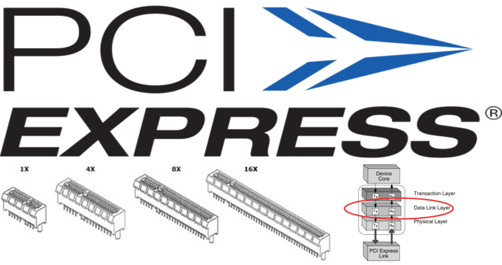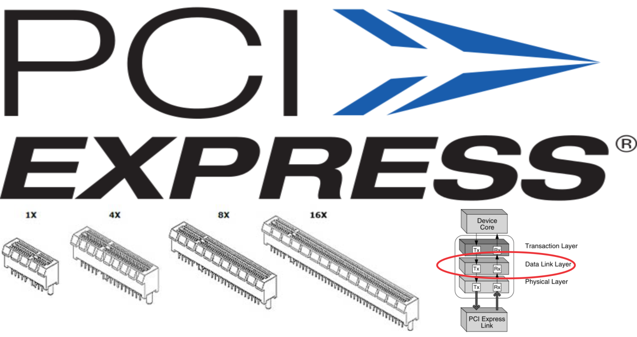
In the last article, i wrote about the physical layer, now let’s take a look in the next layer the data link layer.
The Data Link Layer serves as the “gatekeeper” for each individual link within a PCI Express system. It ensures that the data being sent back and forth across the link is correct and received in the same order it was sent out. The Data Link Layer makes sure that each packet makes it across the link, and makes it across intact.
The Data Link Layer adds a sequence number to the front of the packet and an LCRC error checker to the tail. Once the transmit side of the Data Link Layer has applied these to the TLP, the Data Link Layer forwards it on to the Physical Layer.
For incoming TLPs, the Data Link Layer accepts the packets from the Physical Layer and checks the sequence number and LCRC to make sure the packet is correct. If it is correct, the Data Link Layer removes the sequence number and LCRC, then passes the packet up to the receiver side of the Transaction Layer.
Now let’s talk about theses TLP’s.
The TLP stands for Transaction Layer Packet (TLP) and in the figure below is show a typical packet:
Now there is two main things we need to know:
- Sequence Number – The Data Link Layer assigns a 12-bit sequence number to each TLP as it is passed from the transmit side of its Transaction Layer. The Data Link Layer applies the sequence number, along with a 4-bit reserved field to the front of the TLP.
- LCRC – The Data Link Layer protects the contents of the TLP by using a 32-bit LCRC value. The Data Link Layer calculates the LCRC value based on the TLP received from the Transaction Layer and the sequence number it has just applied. On the receiver side, the first step that the Data Link Layer takes is to check the LCRC value. It does this by applying the same LCRC algorithm to the received TLP (not including the attached 32-bit LCRC).
The data link have three more concepts that you need to be aware of:
- Retries – The transmitter cannot assume that a transaction has been properly received until it gets a proper acknowledgement back from the receiver. If the receiver sends back a Nak (for something like a bad sequence num- ber or LCRC), or fails to send back an Ack in an appropriate amount of time, the transmitter needs to retry all unacknowledged TLPs. To accomplish this, the transmitter implements a Data Link Layer retry buffer
- Data Link Layer Packets (DLLPs) – DLLPs support link operations and are strictly associated with that given link. DLLPs always originate at the Data Link Layer and are differentiated from TLPs when passed between the Data Link Layer and Physical Layer. Additionally, TLPs have an originator and destination that are not necessarily link mates, while a DLLP is always intended for the device on the other side of the link. DLLPs have four major functions (types): Ack DLLP, Nak DLLP, FC DLLPs(Flow Control DLLPs) and PM DLLPs (Power Management DLLPs).
- Data Link Layer Control – The Data Link Layer tracks the state of the link and communicates this status with both the Transaction and the Physical Layer. The Data Link Layer keeps track of the link status via a state machine with the following parameters: States (DL_Inactive, DL_Init and DL_Active) Status Outputs (DL_Down and DL_Up)
Basically the Data-Link Layer will process the sequence number and the LCRC.
If you have any question, leave in the comment section below.
If you want make a request, leave in the comment, this article was a request.
You can check the first and last article about PCIe here, and here.


Facing the Quantum Nature of EUV Lithography