The engineering team for the design and analysis of a complex system consists of a diverse set of skills — with the increasing emphasis on both high-speed interface design and multi-domain power management, a critical constituent of the team is the group of signal integrity (SI) and power integrity (PI) engineers.
The training of SI/PI engineers requires both breadth and depth of understanding of:
- electromagnetic fields
- transmission line theory
- current loop analysis
- RLCG impedance modeling
- decomposition of signal transmission into scattering parameter-based analysis
- frequency-dependent loss calculation
- stripline and microstrip interconnect topologies
- printed circuit board manufacture (including FR-4 glass weave tolerances and line roughness)
- PCB stack-ups, via barrels and antipad design, and
- the cause of resonant impedance in a set of PCB power planes
In short, the SI/PI engineer must be well-versed in a multitude of technical disciplines.
In recognition of the need to assist new SI/PI engineers gain additional experience, Mentor Graphics recently sponsored a full-day intensive SI Bootcamp at their Fremont CA education facility. The day was filled with a mix of lectures, labs, and in the teaching style of Socrates, numerous technical questions posed to the attendees. The instructor was the “Jedi Knight” of SI/PI practical and theoretical education, Eric Bogatin.

Eric began with a unique perspective, to put the audience in the correct mindset. “You need to be the signal — consider the instantaneous impedance, voltage, and current at each step down an interconnect from a driver’s transient. Consider what occurs at each point where the impedance seen by the instantaneous signal changes, and what reflections must occur. And, consider the propagation delay associated with each signal and each reflected transient.”
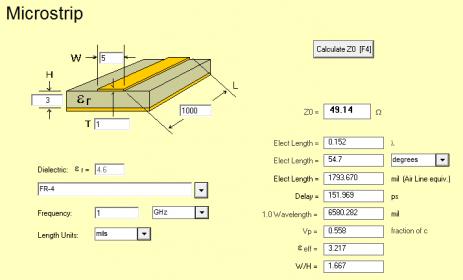
The attendees were encouraged to use the software utilities available in Mentor’s HyperLynx platform to analyze how impedance is dependent upon interconnect topology and PCB materials, to optimize impedance and minimize reflections.

The class was also encouraged to explore the time-based simulation superposition of instantaneous transients, continuing with the “be the signal” theme.
The next topic was to explore a complete model of a interconnect lane, with specific attention on the driver/package parasitics. Labs were included to allow the SI engineer to evaluate the high-frequency content of signal rise/fall times seen at the receiver, and how the composite losses in the model impact that transient. HyperLynx allows the ability to simulate a pseudo-random bit sequence (PRBS) serial stream to plot a superimposed signal arrival at the receiver, commonly referred to as the eye diagram.
A brief review of crosstalk analysis was presented, with insights into how crosstalk transients from an aggressor propagates to both the far-end (FEXT) and near-end (NEXT) of the quiet signal. The “snowball effect” of FEXT along the coupled length of the signal traces was emphasized.
The next topic was the representation of insertion losses in the system using scattering parameter models, including the familiar S-parameter matrix, where the S21 element is the primary representation for the attenuation of V_in when observed at V_out.
Eric shifted gears to discuss the characteristics of a differential signaling interface, from the differential driver’s IBIS model to the receiver. The presentation focused on the perspective of differential mode and common mode analysis, rather than as a pair of separate signals. In this manner, it is easier to understand how energy is converted from differential to common mode, and what differential/common termination strategies are the most effective. Eric challenged the bootcamp cadets to “think about what trace and via design decisions impact the differential impedance, and what should be the impact of topology optimizations, before you simulate — tools should be used to confirm your intuition, not simply to submit iterative testcases.”
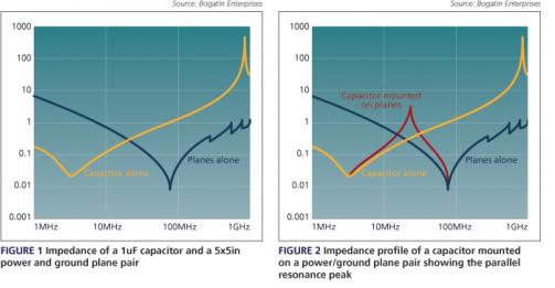
The final topic focused on frequency-dependent power integrity analysis, how the selection and placement of signal and power planes in the stackup (and multi-layer signal vias through anti-pads in power planes) impact the loop currents of the instantaneous signal. An effective visualization for power integrity analysis is the power impedance plot between planes, highlighting the capactive, inductive, and resonant behavior at different frequency intervals. Eric reminded everyone that decoupling capacitors have their own mounting inductance that needs to be included in a composite model of the power plane cavity and decaps. Via-to-via crosstalk analysis requires a co-simulation of the SI/PI model.

At the end of the day, the attendees at the bootcamp review gave Eric a hearty round of applause. It was clear that all gained a greater appreciation of how to apply their academic knowledge to the practical tasks of SI/PI design, optimization and analysis.
If you have an opportunity to attend an SI Bootcamp session, I would strongly encourage you to “enlist”. Eric maintains a set of instructional materials available to SI/PI engineers, with a tremendous amount of video and written information, including a regular newsletter — the link is http://www.bethesignal.com (Not a surprise. :))
Also, Mentor has provided a free, online HyperLynx SI “virtual lab” with some very interesting applications — additional information is available at this link.
-chipguy
Share this post via:


Comments
There are no comments yet.
You must register or log in to view/post comments.