Advanced process nodes create challenges for EDA both in handling ever larger designs and increasing design process complexity.
Shift-left design methodologies for design cycle time compression are one response to this. And this has also forced some rethinking about how to build and optimize design tools and flows.
SemiWiki covered Calibre’s use of a shift-left strategy to target designer productivity a few months ago, focusing on the benefits this can deliver (the “what”). This time we’ll look closer at the “how” – specifically what Siemens call Calibre’s four pillars of optimization (these diagrams are from the Siemens EDA paper on this theme).

Optimizing Physical Verification (PV) means both delivering proven signoff capabilities in a focused and efficient way in the early design stages and extending the range of PV.
Efficient tool and flow Execution isn’t only about leading performance and memory usage. It’s also critical to reduce the time and effort to configure and optimize run configurations.
Debug in early stage verification is increasingly about being able to isolate which violations need fixing now and providing greater help to designers in quickly finding root causes.
Integrating Calibre Correction into the early stage PV flow can save design time and effort by avoiding potential differences between implementation and signoff tool checks.
Reading through the paper, I found it helpful here to think about the design process like this:
Current design
- The portion of the design (block, functional unit, chip) we’re currently interested in
- Has a design state, e.g. pre-implementation, early physical, near final, signoff
Design context
- States of the other design parts around our current design
Verification intent
- What we need to verify now for our current design
- A function of current design state, context and current design objectives and priorities
- Frequently a smaller subset of complete checks
We’ll often have a scenario like that below.
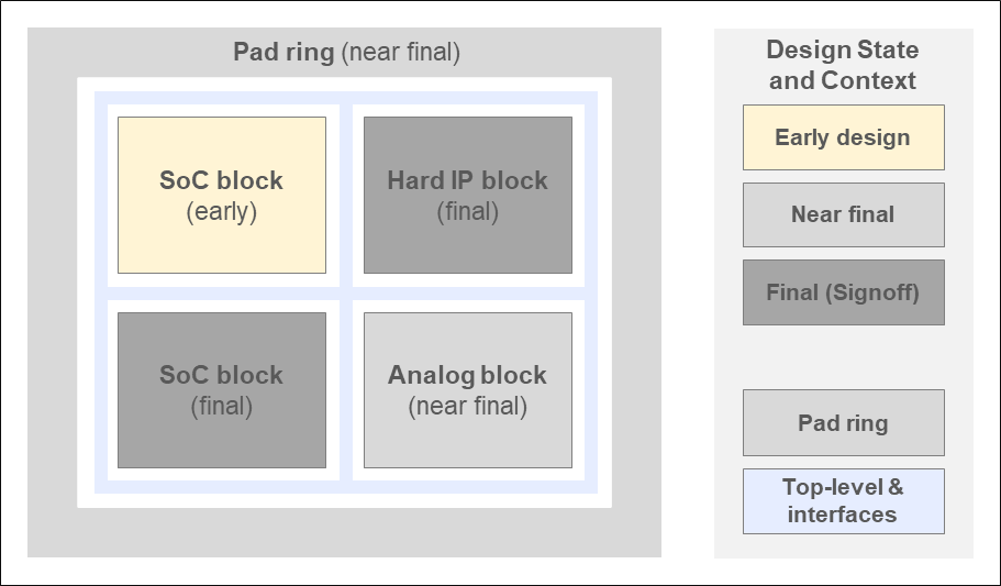
Sometimes we’ll want to suppress checks or filter out results from earlier stage blocks. Sometimes we might just want to check the top-level interfaces. Different teams may be running different checks on the same DB at the same time.
Verification configuration and analysis can have a high engineering cost. How to prevent this multiplying up over the wide set of scenarios to be covered as the design matures ? That’s the real challenge Calibre sets out to meet here by communicating a precise verification intent for each scenario, minimizing preparation, analysis, debug and correction time and effort.
Extending Physical Verification
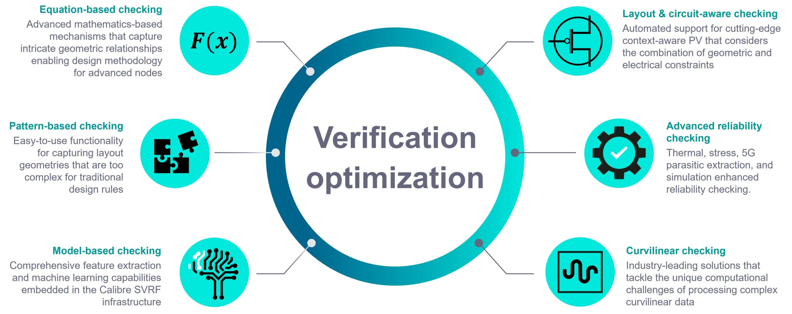
Advanced node physical verification has driven some fundamental changes in both how checks are made and their increased scope and sophistication in the Calibre nmPlatform
Equation-based checks (eqDRC) that require complex mathematical equations using the SVRF (standard verification rule) format are one good example. And also one that emphasizes the importance of more programmable checks and fully integrating both checks and results annotation into the Calibre toolsuite and language infrastructure.
PERC (programmable electrical rule checking) is another expanding space in verification that spans traditional ESD and latch-up to newer checks like voltage dependent DRC.
Then there are thermal and stress analysis for individual chips and 3D stacked packages and emerging techniques like curvilinear layout checks for future support.
The paper provides a useful summary diagram (in far more detail than we can cover here).
Improving Execution Efficiency
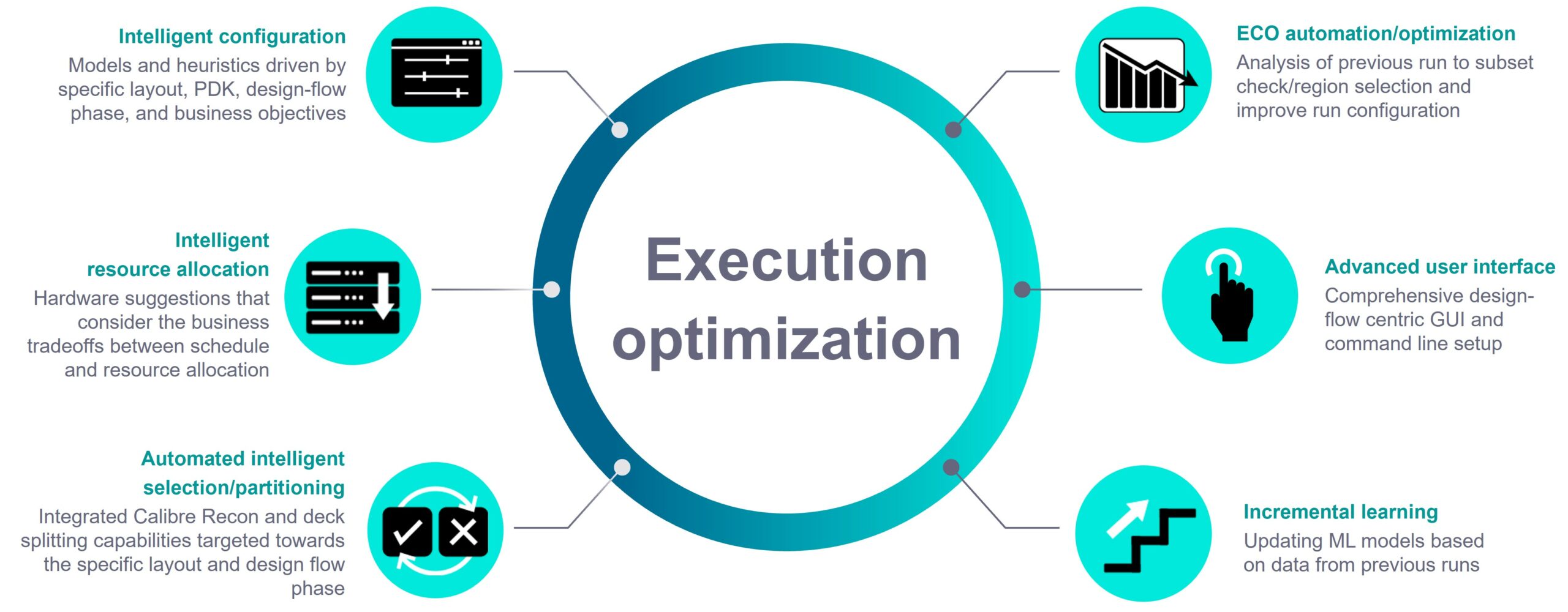
EDA tool configuration is a mix of top-down (design constraints) and bottom-up (tool and implementation settings) – becoming increasingly bottom-up and complex as the flow progresses. But we don’t want all the full time-consuming PV config effort for the early design checks in a shift-left flow.
Calibre swaps out the traditional trial-and-error config search for a smarter, guided and AI-enabled one which understands the designer’s verification intent. Designers might provide details on the expected state (“cleanliness”) of the design and even relevant error types and critical parts of a design, creating targeted check sets that minimize run time.
Some techniques used by Calibre are captured below.
Accelerating Debug
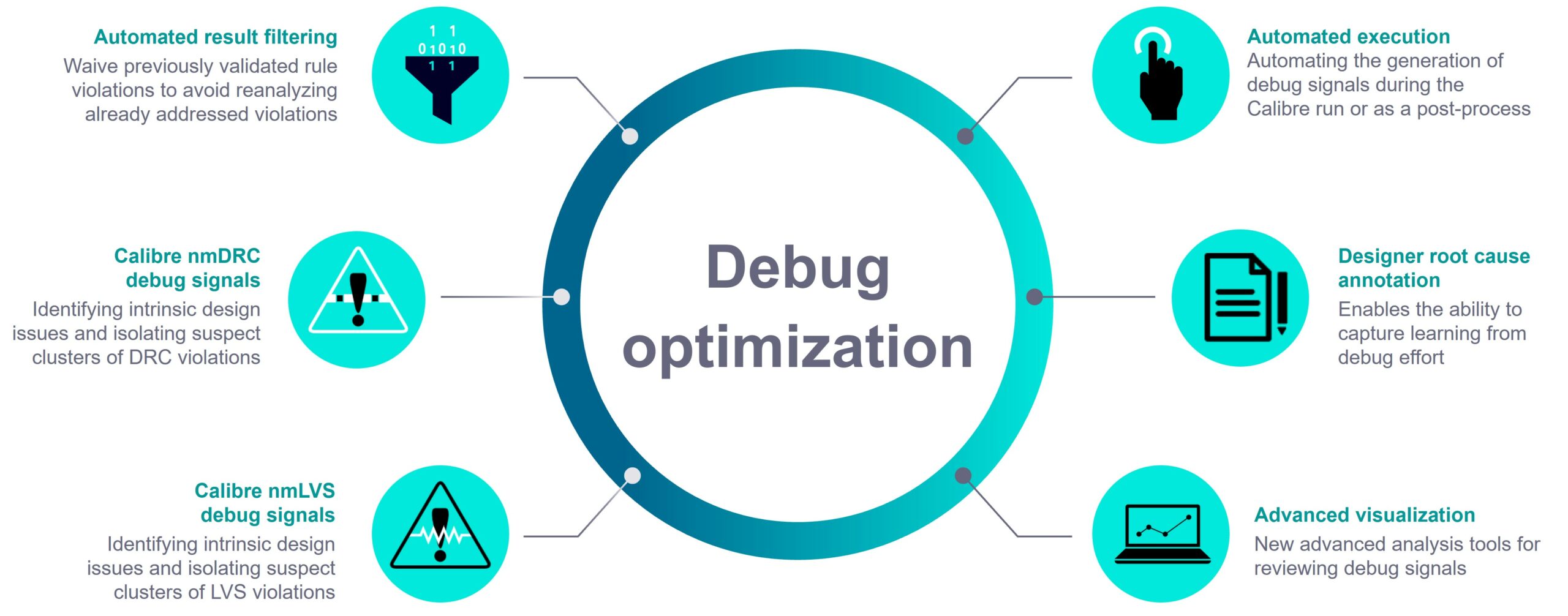
Streamlining checks for the design context usefully raises the signal-to-noise ratio in verification reports. But there’s still work to do in isolating which violations need addressing now (for example, a designer may only need to verify block interfaces) and then finding their root causes.
Calibre puts accumulated experience and design awareness to work to extract valuable hints and clues to common root causes – Calibre’s debug signals. AI-empowered techniques aid designers in analyzing, partitioning, clustering and visualizing the reported errors.
Some of Calibre’s debug capabilities are shown below.
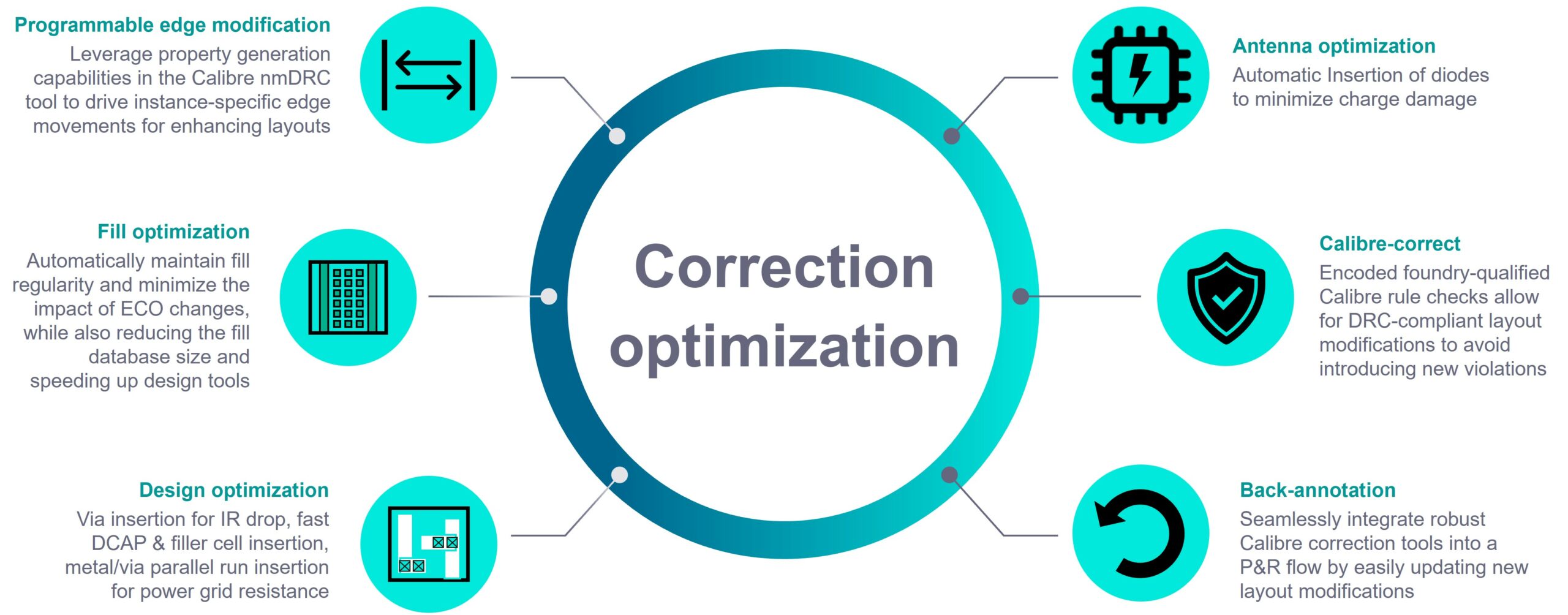
Streamlining Correction
If we’re running Calibre PV in earlier design stages, why not use Calibre’s proven correct-by-construction layout modifications and optimizations from its signoff toolkit for the fixes – eliminating risks from potential differences in implementation and signoff tool checks ? While Calibre’s primarily a verification tool, it’s always had some design fixing capabilities and is already tightly integrated with all leading layout flows.
But the critical reason is that layout tools aren’t always that good at some of the tasks they’ve traditionally been asked to do. Whether that’s slowness in the case of filler insertion or lack of precision in what they do – since they don’t have signoff quality rule-checking – meaning either later rework or increased design margining.
An earlier SemiWiki article specifically covered Calibre Design Enhancer’s capabilities for design correction.
The paper shows some examples of Calibre optimization.
Summary
A recent article about SoC design margins noted how they were originally applied independently at each major design stage. As diminishing returns from process shrinks exposed the costly over-design this allowed, this forced a change to a whole process approach to margining.
It feels like we’re at a similar point with the design flow tools. No longer sufficient to build flows “tools-up” and hope that produces good design flows, instead move to a more “flow-down” approach where we co-optimize EDA tools and design flows.
That’s certainly the direction Calibre’s shift-left strategy is following. building on these four pillars of optimization.

Find more details in the original Siemens EDA paper here:
The four foundational pillars of Calibre shift-left solutions for IC design & implementation flows.
Share this post via:


Comments
There are no comments yet.
You must register or log in to view/post comments.