Reliability of ICs isn’t a new thing, because back in 1980 I was investigating why a DRAM chip using 6um technology was having yield loss due to electromigration effects. I recall looking through a microscope at a DRAM layout and slowly ramping up the Vdd level then suddenly the shiny aluminum interconnect started to change colors and actually bubble because of the high currents, then the metal evaporated. We never could identify the cause of that reliability failure, so it’s kind of haunted me all of these years.
IC designers today will start out a new project by requesting the foundry files for DRC (Design Rule Check), LVS (Layout Versus Schematic) and PEX (Parasitic EXtraction) so that they can perform physical verification tasks to ensure high-yielding silicon and meet timing specifications. In addition to these checks there are an increasing number of reliability checks that need to be done, like:
- ESD (Electro Static Discharge)
- LUP (Latch-up)
- Interconnect reliability
- Electrical overstress
The number one foundry is TSMC, so no surprise that they have also been at the forefront of providing reliability checks for:
- ESD
- LUP
- Point-to-point resistance
- Current Density
- Layout-based rules
Another foundry TowerJazz has been offering reliability checks for automotive IC designers as they follow the ISO 26262 standard for functional safety. These checks include:
- ESD
- Charge Device Model (CDM)
- Analog design constraints
- Device alignment
- Symmetry
- Orientation/parameter matching
Both TSMC and TowerJazz support Mentor’s EDA tool Calibre PERCfor the reliability checks mentioned above.

When adopting a set of foundry reliability design rules you need to understand what these rules are doing, and how your company reliability goals align with them. As a starting point the foundry rules for ESD and LUP can be used, then your team or company can decided to extend the rules to check for certain conditions:
- Each IP is implemented OK
- LUP that is context aware
- Interconnect analysis
- Stacked device in context of full chip
- Power ties correct per well
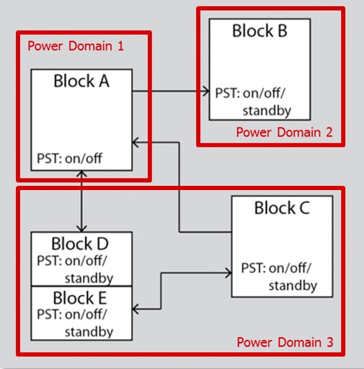
Best practice is to run the reliability checks on each IP block of your chip, so that with final integration there are no surprises that need to be fixed. Reusing IP on a new project but with multiple power domains is another good reason to run reliability checks, as shown below:

Multiple power domains require validation
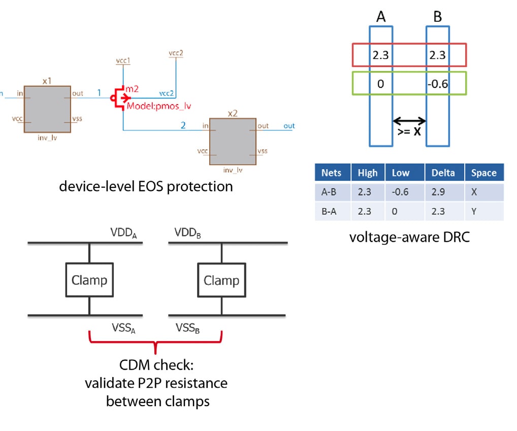
Verifying IP individually is a good start, but not sufficient for full-chip integration because context matters. Here are three cases where context matters:
- ESD and EOS protection
- Voltage-aware DRC
- CDM checking for point-to-point resistance values

Reliability checking with full-chip context
If the bulk node is connected to a higher voltage level than the gate, then it causes a reliability issue for EOS. We do voltage-aware DRC checks to verify that time-dependent dielectric breakdown (TDDB) isn’t happening. Avoiding CDM issues is accomplished through detailed point-to-point resistance checking.
Summary
I’ll never forget the transition from manual DRC and LVS to automated, what a relief for IC designers. The same thing is happening with reliability checks, so start using the foundry-supplied reliability rule checks then add to them as needed for your design and reliability goals. The Calibre PERC tool has been around for a while and it’s ready for your designs and supported by the major foundries.
White Paper
Mentor has an 8 page White Paper on this topic, so start the download process here.
Related Blogs
- Mentor Calibre Panel
- Achieving Clean Design Early with Calibre-RTD
- Foundry Partnership Simplifies Design for Reliability
- Electrical Reliability Verification – Now at Full Chip


Comments
There are no comments yet.
You must register or log in to view/post comments.