hip webinar automating integration workflow 800x100 (1)
WP_Term Object
(
    [term_id] => 157
    [name] => EDA
    [slug] => eda
    [term_group] => 0
    [term_taxonomy_id] => 157
    [taxonomy] => category
    [description] => Electronic Design Automation
    [parent] => 0
    [count] => 3903
    [filter] => raw
    [cat_ID] => 157
    [category_count] => 3903
    [category_description] => Electronic Design Automation
    [cat_name] => EDA
    [category_nicename] => eda
    [category_parent] => 0
)

Clock Domain Crossing (CDC) Verification

Clock Domain Crossing (CDC) Verification
by Paul McLellan on 02-21-2011 at 6:12 pm

Multiple, independent clocks are quintessential in SoCs and other complex ASICs today. In some cases, such as in large communications processors, clock domains may number in the hundreds. Clock domain crossings pose a growing challenge to chip designers, and constitute a major source of design errors–errors that can easily slip past conventional verification tools and make their way into silicon.

When these errors make it into silicon, the costs are high. A single silicon re-spin may cost $10 million and extend time-to-market by months, greatly reducing the chip’s market share and profit potential.

Therefore, there is a substantial benefit to identifying and correcting CDC problems in the early stages of the design, at the RTL level, when corrections may be made quickly and at minimal cost. Unfortunately, cycle-based simulation, the mainstay of RTL-stage verification, is not well suited to finding and tracing timing-related errors resulting from CDC problems. Static timing analysis tools treat clock domain crossings as exceptions and ignore them. Furthermore, traditional structural CDC analysis tools can help identify clock domain crossings and perform some basic synchronization checking, but none offers the kind of comprehensiveness or precision users require. Such tools tend to simultaneously overlook a number of real design errors and over-report a large numbers of false violations.


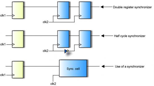
Control signal synchronization


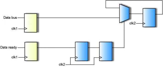
Data signal synchronization

When signals cross from one clock domain to another asynchronous domain, several problems can result:


[LIST=1]

  • Metastability. When a signal from the first clock domain is transitioning just as the second clock domain is clocked, there may be an attempt to clock an invalid logic level into a register. The register may take some time to return to a stable state.
  • Convergence of separately synchronized signals. Since there are times when it is unclear whether a signal will be latched on one clock cycle or the subsequent on, it is possible that two signals changing simultaneously in one clock domain end up a cycle apart in the other domain.
  • Data loss when a signal crosses from a domain with a faster clock to one with a slower clock, for example. More positive synchronization such as handshaking may be necessary

    To detect these problems (and ignore non-problem false errors) a good CDC verification tool must:

    [LIST=1]

  • Identify and display clock domains automatically
  • Identify unsynchronized crossings
  • Screen out false violations
  • Allow users to identify quasi-static signals (e.g. reset signals)
  • Ignore false paths
  • Recognize handshake mechanisms
  • Recognize standard synchronizers, such as 2 flop
  • Allow users to specify non-standard synchronizers
  • Detect problems at synchronized crossings: cross-domain fanouts, cross-domain fanins, reconvergent signals, gray code violations, hold-time violations


    Analysis and display of clock domains

    Images: courtesy Atrenta

    For more details: the Atrenta CDC white-paper


    Share this post via:

  • Comments

    0 Replies to “Clock Domain Crossing (CDC) Verification”

    You must register or log in to view/post comments.