Until now, the integration and testing of IP blocks used in large SOCs has been a manual, time consuming design effort. A new standard called IEEE P1687 (or “IJTAG”) for IP plug-and-play integration is emerging to simplify these tasks. EDA tools are also emerging to support the new standard. Last week mentor announcedTessent IJTAG, which simplifies connecting any number of IJTAG-compliant IP blocks into an integrated, hierarchical network, allowing access to them from a single point. IJTAG will save engineering time by automating design tasks, and potetntially reduce the length of an aggregated test sequence for all the IP blocks in an SOC. This translates into reduced test time and smaller tester memory requirements. For more information on the standard and Tessent IJTAG, click here.
BACKGROUND
In the world of chip design, there are de-facto standards for what information must be included in the library package delivered with a reusable design block, also referred to as an “IP” (i.e., a block of Intellectual Property). Unfortunately, most IP packages do not include information on how to communicate test features or other commands to the block, or any predefined way to integrate specific test features into the overall design. Some IPs, like embedded processors and SerDes I/O interfaces, may come with build-in self-test (BIST) circuitry, but hardly any IP you buy off the shelf comes with a complete, ready-to-go test solution. In addition, there has not been a common protocol to interface to these blocks, so each block requires additional learning and customization to communicate to it.
Consequently, the integration, testing, and communication to IP blocks used in large-scale semiconductor devices has been, to a large extent, a manual design effort. Our customers tell us that integrating hundreds of IP blocks into a comprehensive test plan for a large SoC is becoming vastly more difficult and time consuming. Many of these IP blocks are stand-alone discrete functions such as clock controllers, power management units, thermal sensors, and more. It is necessary to control these IP blocks during testing. Challenges involved in integrating these IP blocks include frequent changes to the design, test engineers being unfamiliar with the blocks, an increasing number and diversity of IP blocks, and complicated operational and test setup sequences to manage.

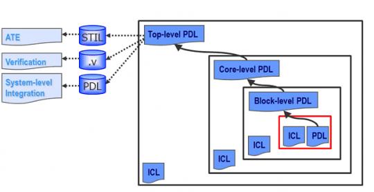
Figure 1. The IEEE P1687 (IJTAG) standard defines two languages, ICL and PDL, that allow the interfaces to a reusable block of IP to be defined in a common manner that enables ply-and-play integration. Tessent IJTAG provides automation support enabling operations on any IP block in a design to be initiated from a single top-level access point.
A NEW STANDARD FOR IP INTEGRATION AND TESTING
To address these IP integration and testing challenges, the IEEE P1687 committee has proposed the IJTAG standard, which builds on the popular IEEE 1149.1 (JTAG) board and card-level test access standard. IJTAG provides a set of uniform methods to describe and access chip internal IP blocks, creating a basis for design, test, or system engineers to easily reuse IP in their products. IJTAG is being defined by a broad coalition of IP vendors, IP users, major ATE companies, and all three of the largest EDA vendors, and is expected to be rapidly and widely adopted by the semiconductor industry.
In the context of IJTAG, the IPs we are referring to are pre-defined blocks of analog, digital or mixed signal circuitry performing particular functions, such as a clock a generator, an interface to an external measurement probe, a radio tuner, an analog signal converter, a digital signal processor, or one of hundreds of other functions. These so-called “embedded instruments” may be internally designed circuit blocks reused across a product line, or 3[SUP]rd[/SUP] party IP purchased from an external source. Typically, they have a control (digital) interface, such as a command register, associated commands and synchronization signals, and a data path. To use the instrument functionality, the designer needs to ensure that defined commands (bit sequences) are sent to the instrument control register in order to reset or initialize it, to set a mode, monitor a state, perform a debug action, or to elicit any other behavior within the instrument’s repertoire. The interface for communicating these control sequences, and the sequences themselves, are defined by the suppliers in a wide variety of different styles with little commonality.
So designers need to create unique logic to integrate each embedded instrument (IP block) into an overall design. For SoCs that often have literally hundreds of instruments from a variety of sources with disparate interface styles, this is a major undertaking that requires lots of engineering time.
This is the problem that IJTAG is designed to solve by providing a method for plug-and-play IP integration enabling communication to all the instruments (IP blocks) from a single test access point (TAP). IJTAG describes a standardized way to define the interface and pattern sequences used by an instrument, and to retarget those commands to any point within an IJTAG-compliant hierarchy. Mentor’s new product, Tessent IJTAG, provides the automation support to implement IJTAG in large, complex designs. Tessent IJTAG can be used to integrate embedded instruments at the die, package, board or system level, providing a single access point at any desired level.
Overview of IEEE P1687
A reusable IP block with a compliant IJTAG digital interface is called an embedded “instrument.” The IJTAG description of an embedded instrument includes its I/O ports and register details as well as the specific sequences needed to control and access the instrument. Both parts are described through P1687 languages defined by the standard: Instrument Connectivity Language (ICL), and Procedural Description Language (PDL).
ICL provides an abstract, hierarchical definition of signals and registers necessary to control the instrument. ICL does not include details of the inner workings of instruments, but only the I/O ports, registers, bit fields, and enumerations of data elements that are necessary to carry out instrument operations. ICL also describes the network connecting all the different instruments. The standard only describes how to accessand control the instruments, and not the details of the instruments themselves.
PDL describes how to operate the instrument through commands and data written to an instrument’s port, and how to monitor the instrument by reading data from the port. These operations are described with respect to the boundaries of the instrument. PDL is compatible with the popular Tcl scripting language.
With the combination of the ICL and PDL descriptions for an instrument and its operations, the instruments can be easily ported between designs. The IJTAG standard ensures that a PDL defined sequence of operations written and verified at the instrument level can be used without modification after that instrument has been included inside a larger design. The automated process of retargeting translates and merges PDL sequences from the instrument’s instance level to the top level of the design (or any other level in between). In other words, Tessent IJTAG reads all the instruments’ PDL definitions and generates new PDL appropriate for the top-level of the design in which the instruments are embedded (Figure 1). Tessent IJTAG can also translate the top level PDL sequences into other formats, such as bit patterns for automatic test equipment (ATE), Verilog files for verification, or system level PDL used for integrating a subsystem into a larger design.
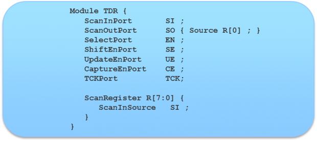
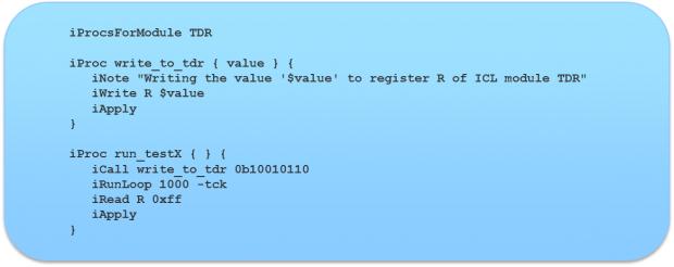
Figure 2 shows the ICL for a typical instrument. It defines an 8-bit shift register named “R”, which receives the command patterns, as well as input and output lines, and several control signals. Figure 2 shows PDL describing actions performed on the instrument. For example, the line “iWrite R $value” causes an 8-bit pattern named $value to be written to register R. Similarly, “iRead R 0xFF” causes the R register to be read and compared to the value 0xFF (i.e., all 8 bits should be 1’s).
Note that the user (e.g., a design or test engineer) simply has to declare the instrument interface and the commands to be given to it. The behavior of all the interfaces complies with IJTAG, so the designer only needs to learn one way to route sequences to the instrument interfaces, and does not have to know the internal details of every instrument as in the past.

Figure 2. The ICL description of a simple embedded instrument interface. Note that IJTAG is not concerned with any of the internal implementation details of the instrument (reusable IP block) itself.

Figure 3. An excerpt of PDL describing some actions to be performed on the embedded instrument from Figure 1, such as writing a value to its command register and reading a value from it.
IJTAG Automation
To fully enable and automate the use of IJTAG, the Tessent IJTAG tool performs four tasks:
- Reads all the ICL and PDL files for a design.
- Performs design rule checks to validate that the instruments and other P1687 components are properly connected to the top-level access point.
- Retargets the PDL description of an instrument to the top level access point.
- Translates the resulting retargeted 1687 PDL into IEEE 1364 Verilog test bench language and standard test vector formats like WGL, STIL or SVF (Serial Vector Format).
Using the ICL and PDL descriptions, Tessent IJTAG will “retarget,” or transform the instrument level PDL patterns to whatever is required at another level in the IJTAG hierarchy. Retargeting to a higher level merges the PDL patterns for multiple IP blocks in a highly efficient manner that results in minimum cycle counts for IP access within a reconfigurable 1687 network. At the top level, the retargeted PDL can be translated into a variety of pattern formats to support further integration, verification and production testing.
SIMPLE EXAMPLE
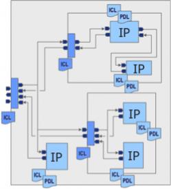
To make this a bit more tangible, consider the simple design in Figure 4. Here five instruments, or IP blocks, have been connected together with paths to a top level access point shown on the left. Each of the five IPs is provided with its own ICL file describing its control interface, and a PDL file describing the operations that can be performed on it. The designer connects these together through a simple network of registers that connect back to a top level IEEE 1149.1-compliant external test access point, or TAP, on the left. The form of these registers and preferred ways to connect them together are recommended in the IJTAG standard, although these mechanisms are very flexible.

Figure 4. Instruments (IP blocks) connected through an IJTAG network to a top level test access point (TAP). Tessent IJTAG automatically retargets the instrument level definitions to the top TAP, enabling control of all IPs from a single access point.
Tessent IJTAG reads all the ICL and PDL files included with the IP blocks and verifies that all instruments are IJTAG compliant. Tessent IJTAG also extracts ICL descriptions for the interconnecting paths to the top level TAP from either a gate level or RTL netlist, and verifies that they are also correct and IJTAG compliant. Tessent IJTAG then uses the ICL and PDL definitions to merge and retarget the instrument PDLs so that all the operations provided by each instrument can be controlled from the top level TAP. From the user’s perspective, causing an operation to happen in any selected instrument is simply a matter of writing a command to the instrument in the top level PDL. Pattern translations, merging and routing happen automatically.
The user can also translate the top level PDL into other types of patterns, such as test vectors to be applied to the top level TAP from automatic test equipment (ATE), or simulation test benches that verify the ICL against the IP’s Verilog description.
To improve ease-of-use and accelerate IJTAG-based test development, the Tessent IJTAG tool has the unique ability to extract (generate) all the ICL network descriptions using the netlist of the overall design. Tessent IJTAG also supports automated creation of the ICL network description to be added to the overall design in case the design does not already contain this network. Using this facility, the user can define how all IJTAG IP will be connected together to a common access point.
SIDE NOTE: JTAG PATTERNS VS. SCANTEST PATTERNS
It is important to differentiate the patterns we are discussing in the IJTAG context from automatic test program generation (ATPG), which typically refers to test patterns designed to stimulate structural or “scan chain” testing within a digital IC. Scan tests are used to detect defects within a manufactured IC by inserting a pattern of ones and zeros that propagate through the logic, and comparing the resulting internal states to the expected result. A mismatch indicates a defect in the implementation of the logic circuitry (a design defect) or in the manufacture of the device (a manufacturing defect). Scan test patterns are automatically derived from the actual circuit logic during the ATPG process and are distinct from the command sequences applied to an instrument interface to set a mode or initiate an operation in the block.
In the IJTAG context, a test engineer may perform a test on an instrument by using the IJTAG interface, for example, by putting it into a known state and then using a monitoring command to read back a value from the some point inside the instrument. However, this is quite different than a scan pattern set.
Tessent IJTAG can be used together with ATPG because scan testing typically requires that the logic to be tested must be initialized and certain modes must be set before scan testing can commence. IJTAG can be used to perform these setup and mode control functions. For example, test setup may require enabling power and clock domains across the design, programming PLL output waveforms, putting instruments into a “bypass” mode, or switching instruments in and out of the test scope, to name just a few of the possible usages. All these tasks can be done efficiently through an IJTAG network before the ATPG patterns are computed (when the test patterns are being generated) or applied (during production testing). In this scenario, the command patterns defined by the retargeted top level PDL could be combined with the scan test ATPG pattern set as a single test vector file. However, generating the scan patterns themselves is not done by Tessent IJTAG, but in a separate operation performed by Tessent FastScan or TestKompress.
Share this post via:


Comments
There are no comments yet.
You must register or log in to view/post comments.