April 25, 2013, San Jose, CA
Click here to register.
Come hear Mentor Graphics CEO, Wally Rhines, 2013 Kaufman Award Winner,Chenming Hu, and Xilinx Senior VP,Victor Peng, at the User2User Conference in San Jose.
KEYNOTES
Organizing by Design
9:00am – 9:50am
Walden C. Rhines | CEO & Chairman | Mentor Graphics
Winning products are rarely the result of optimizing only one aspect of a design. Innovators generate success because they find ways to cross organizational and functional boundaries to optimize a product in multiple disciplines. Mature companies try to solve this problem by creating cross-disciplinary teams while startup companies do it naturally due to lack of enough resources to allow specialization. Meanwhile, products targeted at customers in different disciplines rarely appeal to more than one. Dr. Rhines has compiled data on cross-disciplinary product successes including attempts by companies to create products for hardware/software co-design, mechanical/electrical design integration and many more. He has identified successes and categorized the ways that companies have (rarely) achieved multi-disciplinary product optimization. He will use these examples to generate some guidelines for companies of all sizes to achieve product development success.
The New Era of Heterogeneous Architectures and Integration Technologies
10:00am – 10:50am
Victor Peng | Senior VP of Programmable Platform Group | Xilinx
Since the first integrated circuit was demonstrated in 1959, transistor density has increased by a factor of a billion and in the process has changed the world. However, despite the integration levels possible at advanced nodes like 28nm, the vast majority of high performance analog and high density memory chips have been and continue to be built with technologies distinct from high performance digital chips due to conflicting technology requirements. Another megatrend is the explosion in the cost of developing ICs in advanced nodes while the cost reduction benefit from moving to an advanced node has been disappearing. In this new era of integrated circuits the next wave of innovation will come in the form of heterogeneous architectures and products realized with 3D IC integration technologies. This talk will describe how Xilinx is enabling heterogeneous architectures and products as well as the underlying technologies required to realize them.
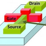
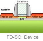
FinFET is a Beginning
1:00pm – 1:50pm
Dr. Chenming Hu | TSMC Chair Professor of Graduate School | Univ. of California, Berkeley
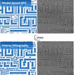
FinFET overcomes the impending show stopper that device physics imposes. The ultra-thin-body concept, which FinFET embodies, may lead to more new structures and materials research directions that can give relief for other future show stoppers such as the high cost of scaling by lithography. Dr. Hu is the 2013Kaufman Award winner for distinguished contributions to EDA.
TECHNICAL SESSIONS
Practical Tips to Increase Productivity and Communication with Calibre
11:00am – 11:30am
Joseph Davis | Marketing Director | Mentor Graphics
Just running physical or electrical verification is only part of the battle of getting your chip to Tape-out. We will show practical applications of how to minimize your debug time, minimize manual steps, and improve communications between team members and with your foundry. These applications are appropriate for both custom and digital design flows and leverage the Calibre tool set that you already own.
Meeting the Turn-Around Time Challenges for Sign-Off Extraction
11:30am – 12:00pm
Carey Robertson | Product Marketing Director | Mentor Graphics
Achieving design closure is increasingly difficult with new manufacturing effects creating modeling challenges and driving the need for additional interconnect corners at advanced nodes. Most customers are not using Calibre for Sign-Off Extraction. xACT SOC will change that and this session will introduce how this solution can accurately model interconnect at all nodes as well as achieve performance and scalability that is unmatched by competitive offerings.
Custom Place and Route Layout Enhancement Using Calibre with Timing Verification
2:00pm – 2:40pm
Shobit Malik | Senior Member Technical Staff | GLOBALFOUNDRIES
Christian Hauf | MTS< Member of Technical Staff | GLOBALFOUNDRIES
Sriram MAdhavan | PMTS, Principal Member of Technical Staff | GLOBALFOUNDRIES
Ahmed Mohyeldin | MTS, Member of Technical Staff | GLOBALFOUNDRIES
James Paris | Technical Marketing Engineer | Mentor Graphics
At advanced process technology nodes, design for manufacturability techniques like redundant via insertion and via line end extensions are known to be critical for improved yield and reliability. For digital designs, the router is used to insert redundancy in terms of more vias, large metal area as well as metal enclosure without growing area to make a design manufacturable. Since a router’s primary goal is to place and route a design in a limited amount of space, it is limited in its capability to push the insertion of redundant geometries. Hence, we use a custom solution whose primary focus is to insert a maximum of redundant geometries to make a design more manufacturable. These geometries are added within existing open space without growing existing space or touching existing layout using internally developed tool Y.E.S (Yield Enhancement Suite).
Since Y.E.S is a post place and route enhancement, it restricted us from verifying the timing impact as these changes are done on layout outside of the router’s database. This restriction limited the application of Y.E.S in the digital world since a proper sign off process required timing validation for all layout changes or enhancements done.
In this presentation we share our approach to use Y.E.S (or a similar post layout optimization tool) with the ability to back annotate it’s layout changes into a router’s database. We discuss the flow used to do this back annotation and show as an example our implementation where we imported these layout changes into MilkyWay database.
Layout Dependent Effects: Checking Number of Fingers with a Calibre-Based Flow
2:50pm – 3:30pm
Bruce Leong | Principal Hardware Engineer | Oracle
Starting with the 28nm process node, physics plays an even more important role in device performance. Layout practices must be changed in order to match modeling. Among these issues is matching the exact number of fingers for a device in the layout as specified by the circuit designer in the schematic. A method is described using Calibre LVS, the Query Server, a netlist flattener, and RVE output to achieve this matching.
Design Reliability with Calibre Smart-Fill and PERC
3:40pm – 4:20pm
Muni Mohan | Engineering Manager | Broadcom
This presentation dwells on improving design reliability and yield models with Calibre SmartFill and Calibre® PERC™.
The complexity of advanced technologies drives new requirements for poly/OD and metal fill to solve critical manufacturing effects, and more importantly design yields. New methodologies were developed for 28nm designs using Calibre SmartFill to meet the new strict DFM requirements while reducing run time, file size and iterations.
Besides manufacturing process, electrical rule checks can also significantly impact design yields & reliability. Identifying incorrectly configured devices, multi-power domain transition guides, and floating (leaky) gates is critically important right from the circuit stage, well before physical layouts. Such early design consistency checks written with rules in Calibre® PERC™ help us catch design mistakes early on, and validate some of our high reliability design metrics.
Both Calibre Smart-Fill and Calibre® PERC™ were significantly and successfully deployed on our largest 28nm tapeout recently.
Synopsys Laker Custom Layout and Calibre Interfaces: Putting Calibre Confidence in Your Custom Design Flow
4:30pm – 5:10pm
Dave Reed | Director of Marketing | Synopsys
Joesph Davis | Marketing Director | Mentor Graphics
While every design must pass sign-off before going to the foundry, it is inefficient to wait until the very end of the design process to run the sign-off checks. For this reason, Calibre provides interfaces to both custom and digital design tools which enable engineers to check against the sign-off decks throughout the design process. Through close cooperation between Mentor and Synopsys, Synopsys Laker users can check with Calibre “on the fly” during design to speed creation of design-rule correct layout, including electrically-aware voltage-dependent DRC checks.