llmda newsletter ad (2)

Automotive Artificial Intelligence (AI) Insights from Patents

Automotive Artificial Intelligence (AI) Insights from Patents
by Alex G. Lee on 03-29-2016 at 7:00 am

US9254824 illustrates an adaptive anti-collision system for providing timely alert information by analyzing the driving pattern of the driver using a neural network. A neural network utilizes massive connected artificial neurons to mimic the capability of a biological neural network so as to acquire information from external environment. In essence, a neural network is an attempt to simulate the human brain.

The adaptive anti-collision system determines the driving pattern corresponding to a vehicle speed, a safe distance and a braking distance based on the vehicle speed or acceleration, road condition, and drivers’ driving behavior using the neural network. Then, the adaptive anti-collision system adjusts control parameters of the vehicle (e.g., safe distance) control unit dynamically according to the driving pattern to issue an alert or activate a braking action.

US20140108307 illustrates a system for providing personalized and context-based suggestions to a driver using a machine learning. For instance, the system obtains contextual information indicating that a contact of the driver is only a few minutes in driving time from the driver’s route. Further, based on social communications and social media information stored in the driver profile, the system also determines that the contact is a friend of the driver. Based on that determination, the system informs the driver, “Your friend Peter is at a few minutes away from your route; would you like meet?”

US20150302718 illustrates a system for correlating physiological signals associated with a driver with vehicle-related events using a machine learning. Physiological signals include sensed and monitored data regarding the heart-rate, oxygen use, eye motion, galvanic skin response, blood flow, pupil dilation, and facial expression. Vehicle-related events include traffic, weather, visibility, road conditions, accidents, traffic alerts, distance-from-other vehicles. Vehicle-related events can be determined and communicated through external sources (e.g., cloud-data, inter-vehicle communication) as well as the vehicle’s controller-area network.

Based on the vehicle event data and physiological data, a driver state is then determined by correlating the vehicle event data with the physiological data associated with the driver using the machine learning. The driver state includes a level of driver stress, a level of driver drowsiness, a level of fear of the driver, a state correlated to the event of overtaking another driver, and a state correlating to the event of being overtaken by another driver. The system provides a suggested action based on the state of the driver. For example, the system determines that the driver becomes angry or nervous when in heavy traffic. The system then suggests to the driver that the channel on the audio system be changed to provide relatively soothing music.

US8190319 illustrates an adaptive real-time driver advisory control system for a hybrid electric vehicle to achieve fuel economy improvement using a fuzzy logic. A fuzzy logic-based adaptive algorithm with a learning capability can estimate a driver’s long term driving preferences. The advisory control system uses a set of rules with fuzzy predicates and an approximate reasoning method to summarize a strategy that accounts for instantaneous fuel consumption, vehicle speed, vehicle acceleration, and the driver’s torque request, in order to determine the upper bound of the torque request that accounts for maximum fuel efficiency and drivability. The advisory control system then provides feedback to the driver such that the fuel economy of the vehicle can be improved in a real world driving environment.


Yelling fire in a crowded chip factory

Yelling fire in a crowded chip factory
by Don Dingee on 03-28-2016 at 4:00 pm

Semiconductor market forecasts for 2016 are all over the place. Jim Handy and Tom Starnes floated a report in January looking for 10% growth. Jim Feldhan at Semico turned outright negative at -0.3% just a couple weeks ago. Tossing out the high and low scores, analysts tracked by GSA range from 0.3% to 7.0% in March updates. What’s going on here?

I’m not an analyst, I’m a product marketer. My job for the last 25 years has been to watch trends, gather facts and opinions, and sort out where and how to place the bets that best utilize engineering, manufacturing, and sales resources. Whenever someone comes up with a forecast number, I always ask how they got there.

Reading through the latest reports and opinions, a few things jump out. Semico’s opinion is based on their Inflection Point Indicator, a leading model with four quarters of advance visibility. It’s hard to say what is in Feldhan’s recipe exactly, although he gives hints – in his view, GDP growth of major economies other than India are slowing, DRAM is weakening in both demand and ASP, and the big application segments of PC and mobile are in non-regenerative braking modes.

Bill Jewell of Semiconductor Intelligence has already shared his latest opinion on SemiWiki, and he’s settling in at around 3%. He points to an electronics slowdown in China (from incredible 14% levels to a more reasonable 10%) while showing a jump in the US to 6.5%. Jewell cites near-term reduced global revenue guidance from most semiconductor firms, but says something very interesting and potentially messy in his text:

“We are assuming a decline of 5% in 1Q 2016, healthy quarter-to-quarter growth in 2Q and 3Q 2016, and a mild seasonal decline in 4Q 2016.”

Meanwhile, the low end comes from the SIA itself, dialing down its number to 0.3%. Their formula is pretty simple – the $45B DRAM segment sheds -7.9%, while most other segments grow, including sensors at 3.6%, microprocessors and MCUs at 3.6%, and logic including ASICs and FPGAs at 3.5%.

Then there is the Objective Analysis high end. They use a cap ex analysis as a major component of their model. They cite the IoT as (still) being 5 years away, and an overreliance on China for growth. However, their model factors in DRAM and NAND flash capacity, and they suggest two things are happening. First is a switchover from DRAM to NAND (something we pointed out in our Samsung chapter in “Mobile Unleashed” – their fab capacity is largely interchangeable). Second is while ASPs are flattening, bit capacity is growing, 20% for DRAM and 35% for FLASH, which translates to an estimated 14% revenue growth in the memory segment.

My conclusion from all that is, unlike the PC days when a microprocessor carried everything else in mass quantities along for the ride, there is no such thing as the semiconductor market anymore. Component categories are not moving in lockstep, and there is no clear trend in geographic markets. One really has to break this down by application segment to understand what could be happening. That’s one of the problems with IoT forecasting – it isn’t really a segment, but rather a collection of technologies and a hodgepodge of use cases that make it hard to say with certainty what happens five years out.

Of course, all the analysts claim to be accurate within a statistical margin. I’d add one factor I didn’t see anyone talk about – a pronounced shift from merchant business to custom or semicustom business, which is a lot harder for analysts to get their arms around. Cap ex may also be a bit misleading outside of the memory segment for this next phase, because much of the IoT activity is going to be on mature processes already in place.

OK, so I’ll put my money where my mouth is. I don’t have any sophisticated model here that would produce a decimal place of accuracy. My best guess at the semiconductor “market” would be 2% growth for 2016, however if one were to remove DRAM, that number would be more like 4%. The mere fact DRAM is dragging the market not due to overcapacity issues says a lot.

Which pieces of these methodologies pass the sniff test for you? Should we stop calling this a market and do what the SIA is suggesting, analyzing growth rates by component segment? If it isn’t the IoT, what will trigger semiconductors to outperform GDP growth rates again – or is that not going to happen anytime soon? Thoughts welcome.

References for this post:
2016 Forecasts – Global Semiconductor Alliance
2016 Semiconductor Sales Go Negative– Semico Research
2015 semiconductor market flat, 2016 looking somewhat better – Semiconductor Intelligence
Semi Market Breakdown and 2016 Forecasts – EETimes
2015 Reflections and 2016 Outlook – Objective Analysis


Bridging Design Environments for Advanced Multi-Die Package Verification

Bridging Design Environments for Advanced Multi-Die Package Verification
by Tom Dillinger on 03-28-2016 at 12:00 pm

This year is shaping up to be an inflection point, when multi-die packaging technology will experience tremendous market growth. Advanced 2.5D/3D package offerings have been available for several years, utilizing a variety of technologies to serve as the package substrate, interposer material for embedding die micro-bump fan-out redistribution and interconnect metals, and (for 3D stacks) the method for fabricating vertical vias through intermediate package/die strata. Some recent examples include the Xilinx UltraScale product family (TSMC’s CoWoS technology) and AMD’s Radeon R9 integration of a GPU with stacked High Bandwidth Memory (HBM) die.

This year, the market growth will come from packaging technology enhancements directed at more cost-sensitive (read: mobile) applications. Wafer-level chip-scale packaging (fan-in WLCSP) has been extended to fan-out packages, and soon, fan-out multi-die solutions, as exemplified by TSMC’s recent InFO-PoP announcement.

Yet, the design environments for die and package implementation remain separate — i.e., distinct tools for chip vs. package physical design, distinct rulesets for DFM, distinct project databases and manufacturing data formats (e.g., GDS-II, Gerber). A unique technology is required to bridge these different domains, and provide an integrated design verification solution.

Recently, I had the opportunity to chat with John Park and John Ferguson at Mentor Graphics, about their approach to advanced packaging design enablement, and specifically, their participation with TSMC as a constituent of the “reference flow” for InFO-PoP. It was a most enlightening discussion.

John P. emphasized the complexity of dealing with the chip and package implementation domains. He said, “For a designer coming from the chip world, the biggest technology difference for advanced packaging is the routing environment for fan-out and signal interconnects. These traces utilize all-angle geometries, circular vias, and unique teardrop and taper contours.”

He highlighted another complexity, stating, “For the aggressive fan-out technologies like InFO, there are intricate manufacturability rules for copper meshing and voids, to provide suitable mechanical stress relief to minimize warpage, and to alleviate copper pour outgassing issues.”

John P. went into additional detail, on how Mentor has extended their leading Calibre product capabilities to support advanced packaging technologies. “The key is the geometric data processing engines integrated into Calibre 3DSTACK, which were required by the WLP technology design kit from TSMC. Their design rules make extensive use of the equation-based DRC support in Calibre — which are similar to the complex rules in Photonics technology design kits. And, Calibre supports multiple designs in a single project, a requirement for these packages.”

He continued, “These features enabled TSMC to use GDS-II as the InFO data representation, and for the familiar Calibre sign-off for manufacturing release flow already used by customers. We also enhanced the GDS-II rendering support in our Xpedition product, to support using GDS-II.”

John F. added, “There’s a subtlety that we have to manage, as well — as there are separate sources for die and package data, there may be overloaded uses of manufacturing layer info. The flow ensures that there are no conflicts in layer references.”

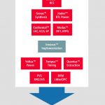
The flow for advanced multi-die package verification is appended below.

The initial step is to utilize the features of Xpedition Package Integrator (XPI in the diagram), which focuses on constructing the multi-die project connectivity model from the various, EDA-neutral, data formats. (An earlier semiwiki article described some of the features of XPI here.)

John F. added, “The Calibre 3DSTACK capabilities for multidie package verification are definitely not limited to Xpedition users; other environments are certainly supported (e.g., Cadence Allegro Package Designer, Zuken). For Xpedition users, there is the added benefit of an available WLP design kit utilizing Hyperlynx DRC, that enables designers to remain in the (Windows O/S) tool environment, to iterate more quickly.” (as depicted in the lower right-hand corner of the flow diagram)

“Also, debug results from the (Linux-based) Calibre sign-off flow are directly integrated in Xpedition, with cross-probing between Calibre result and Xpedition geometry.” (illustrated in the figure below)

Our discussion concluded with the all-important reminder that these advanced packaging solutions require detailed thermal/mechanical stress analysis, another area where Mentor’s support excels.

The rapid pace of development for (low-cost, small form-factor) multi-die packaging solutions has necessitated a focus on providing reference flows for verification, that support interoperability in chip and package design environments. Mentor has addressed this requirement through extensions to their Xpedition product family, and through the introduction of Calibre 3DSTACK (which does not require a new license, by the way). Design kits and reference flows are available.

It will be exciting to see how end products released later this year will leverage this advanced packaging technology.

For more info on Calibre 3DSTACK, please follow this link.

-chipguy


IC Design Optimization for Radiation Hardening

IC Design Optimization for Radiation Hardening
by Daniel Payne on 03-28-2016 at 7:00 am

I was born in 1957, the same year that the Soviets launched the first satellite into Earth orbit, officially starting the Space Race between two global super powers. Today there are many countries engaged in space research and I just read about how engineers at IEAv (Institute for Advanced Studies) in Brazil did their IC design optimization for radiation hardening. The CITAR project has multiple institutions collaborating to create ICs for satellites used in the Brazilian space program:

  • Design ICs – Centro de Tecnologia da Informacao Renato Archer
  • Radiation Tests – IEAv, USP, FEI
  • End User – INPE

In space there are cosmic rays that create trapped particles like protons, electrons and heavy ions. These particles effect ICs in orbit in a variety of ways:

  • Vth of the P and N channel MOS transistors will shift up or down
  • The sub-threshold slope increases
  • Leakage currents increase
  • Mobility is decreased

Circuit designers need to know how these particle induced effects in satellites will change the performance of an IC over time. The Total Ionizing Dose (TID) defines the extent of radiation effects. Fortunately the researchers can create radiation models here on Earth by running radiation experiments. On this IC project the chip engineers optimized their circuits for use in a rad-hard environment by using an optimization tool called WiCkeD from EDA supplier MunEDA.

Their old design methodology was updated to include rad-hard optimization using WiCkeD as shown below:

A bandgap circuit from the XFAB reference kit was optimized in this new design flow using the XH018 process. The specifications for this circuit are:

The goal is to load both the standard model and rad-hard model into WiCkeD, then optimize the circuit to pass all corner cases.

Step one is to use this circuit with initial values of Width and Length devices at a nominal corner and see how the circuit performs against the specifications. They found that both minVBG and TC were violating the specification for this initial corner.

Step two is to run Deterministic Nominal Optimization (DNO) to improve the design so that it passes all specifications. After a few DNO iterations the circuit now passes the specifications:

In robustness verification they found good results over all operating conditions. The yield estimated by 200 samples of Monte-Carlo Analysis is 99.5%, and a Worst Case Analysis showed that all specifications could be achieved with a robustness of at least 2.58 sigma:

Yield Optimization was the next step and this is where they ran corners with the fresh models and corners with the rad-hard models to see what the mismatch effects were. Robustness verification of Yield Optimization (YO) showed that all specifications could be achieved with a robustness of at least 3.21 sigma:

Here’s a quick comparison of device sizes after each optimization step:

The yield optimizer (YO) improved the robustness against random variation at worst-case corners, operating conditions, and radiation from 2.6 to 3.2 sigma without increasing the area, only be re-balancing the transistor geometries.

Summary

IC designers can optimize their circuits for rad-hard environments found in orbit by using EDA tools like WiCkeD from MunEDA. Engineers on this particular project took about two weeks elapsed time to optimize their circuits, taking about 18,000 simulations for the entire design flow.

IRPS Conference

On April 21st at the International Reliability Physics Symposiumthere’s an interesting paper from STMicroelectronics and MunEDA titled, “BTI Induced Dispersion: Challenges and Opportunities for SRAM Bit Cell Optimization“. This paper presents at 1:30PM and here’s the abstract:One major CMOS reliability concern for advanced nodes is the Bias Temperature Instability (BTI)mechanism. In addition to the native local process dispersion, the BTI induced dispersion is a field underintensive research. Important works [1, 2] focus on the distribution tail of the Vth shift and efforts aredeployed to high-sigma accurate modeling (defect centric, Skellam). In most applications influenced bydevices matching (ADC, SRAM…), it is important to understand how the initial Vth distribution evolvesin time. In this paper some key results of spread induced by BTI are reviewed for 14FDSOI and 28FDSOIfrom STMicroelectronics. Analysis between initial Vth and aged Vth correlation is presented. Then,measurement of fresh and post HTOL memory VDDmin is presented for different conditions of temperatureand process centering. Finally, an innovative algorithm of yield optimization is presented. It enables tooptimize the centering and yield (through devices sizing or process centering) including ageing, underconstraint of foot print.

Related Blogs


IoT Workshop in Beautiful Monterey California!

IoT Workshop in Beautiful Monterey California!
by Daniel Nenni on 03-27-2016 at 8:00 pm

It is that time of year again, the EDPS Workshop at the Tides Hotel in Monterey. This year will start out with a keynote on IoT from Serge Leef, VP of New Ventures and GM of the System-level Engineering Division at Mentor Graphics. Serge started his career at Intel followed by Microchip and Silicon Graphics. He has been at Mentor for the last 26 years. So yes, this is going to be an interesting session because new ventures and system-level engineering equals IoT, absolutely. And remember this is a workshop so you get to interact with industry experts at a much more personal level:

Keynote: Convergence of silicon, Sensors, Mobility, and Cloud as Driving Forces in System Design Evolution

IoT is not an abstract concept whose existence needs to be debated. It is a reality in the evolving computational landscape. Embedded systems that have once encapsulated a finite feature set in a fixed formed factor (i.e. box) are morphing into disaggregated solutions made up of loosely connected edge nodes talking to gateways which are in turn linked to the cloud. Cloud APIs exposed to web based and mobile apps, unleash creativity of huge communities of developers who can turn, once static, devices into machines with open-ended functionality bounded only by imagination.

IoT is merely an implementation detail that is not “front and center” when the value of end-to-end vertical applications is pitched to the VCs these days. IoT works behind the scenes to enable seamless and readily observable value to be delivered to a consumer. Smart garage door openers and door locks, weather and moisture driven sprinklers, real time patient monitoring and diagnostics, indoor climate and humidity controls are all enabled by the advancements in several technologies that are maturing all at once. This is creating a gold rush as people with ingenious ideas leverage their domain expertise to create uniquely valuable devices and services enabled by rapid advances in sensors, mobility, connectivity, cloud, standard communication protocols and predictive data analytics.

For the engineers the new computational topology presents fascinating challenges. Where in this world do you place the algorithms? An accepted approach is to assign the most demanding processing that requires limited data movement to the cloud, where computational and storage resources are essentially unlimited. Additional processing can be directed at “fog computing” on the gateways which are typically very capable computers containing quad-core processors and can benefit from physical proximity to the edge nodes and low data communications costs. Lastly, some computation can be done on the edge nodes (“mist computing”) where sensors and actuators coexist with low-power CPUs and memories in small, battery powered devices.

The IoT world presents fascinating new opportunities in software. In addition to much discussed and increasingly well understood topic of big data analytics another area of deriving insight from newly available data is emerging: sensor fusion. As dozens of sensor can deliver volumes of readings in real time, an opportunity exists to collect, organize, correlate and process the incoming data turning it into information which can then be translated into knowledge. Doing something with this knowledge and turning it into wisdom is a big domain specific challenge and opportunity. Many consider autonomous driving to be the perfect application domain for experimenting with sensor fusion. Other obvious sensor fusion application areas are medical diagnostics, industrial controls, energy management, etc.

An aspect not to be overlooked in all this excitement is security. With forecasts of 20B – 50B connected devices by 2020, it’s easy to see that security as a concern will soon come to the foreground. Huge number of internet connected devices with highly variable levels of security sophistication will create a massive attack surface for the hackers. While the app world, the cloud and the gateways contain built-in security layers and countermeasures, the edge nodes are the ultimate “soft targets”. Unfortunately, it will probably take a few highly publicized breaches to instill a security discipline throughout the entire IoT chain.

More Information on EDPS HERE… Early bird registration ends April 1st…


Growing Security Concerns Due To Internet of Things (IoT)

Growing Security Concerns Due To Internet of Things (IoT)
by Faisal Mushtaq on 03-27-2016 at 4:00 pm

It is believed that by 2020, there will be about 50 billion connected devices across the world, more than 7 times the present human population. The growth of digital devices is increasing exponentially because both users and technology are getting smarter every next day and the compatibility between the two is improving phenomenally with the unprecedented growth in the internet, mobile, robotics and IT technologies. Ubiquitous computing, ubiquitous use of IP and ubiquitous connectivity are the three major propellers of the IoT, and that’s why it has been successful in bringing disruptive transformation in all spheres of the human life. Today, the IoT is responsible for almost every digital communication, from Telephony to Emailing and Machine-to-Human communication (M2H) to Vehicle Telematics, all are grossly dependent on the IoT.

How the IoT is Surrounded By Incessant Threats?
An IoT network is very much required today for data collection, closed loop functioning and network resource preservation, and all of these procedures are terribly prone to risk and threats. On the other hand, it is very clear that moving without using the latest technology is like moving into a dark and directionless world, and success of businesses as well as the nations completely relies on the adoption of the IoT. But, are you aware that stalkers are always following you? They stealthily try to eavesdrop your messages and if you are not moving through a safe alley, from simple espionage to an easy access to intellectual property, there are enough chances that they will ambush upon your network and do everything to steal the data, which is the be-all and end-all of your business.

If you love tracking news then you might have heard about the ONGC case. In the recent past, one of the Navratna of India’s public sector, the Oil and Natural Gas Corporation Limited (ONGC) lost Rs. 197 crore when the perpetrators successfully made access to the official email account of an employee. They duplicated the public sector firm’s official e-mail address and used it to convince an overseas client to make the payment of a Rs. 197 crore deal. It is just one case in the huge Pandora box of the IoT threats.

How to Combat the IoT Threats?

We should always make ourselves ensured that the technology we are using is safe and we are moving in a protected environment. Because the more we are dependent on the IoT, the more vulnerable we are to espionage, phishing, ransomeware and system hacking. Therefore, to protect data and other useful information, businesses and government agencies must establish a stringent security system based on the four key components of the security framework viz., Authentication, Authorization, Network Enforced Policy and Secure Analytics. The Defense Research and Development Organization (DRDO) of India have chosen Multifactor Authentication solution for the effective re-validation of the credentials & authenticity of the users into the organization’s ERP. In addition to Multifactor Authentication, Data Leak Protection, Advanced Persistent Threat Protection, and IPS/ Firewall can help greatly reduce the risks.


Improvements in SRAM Yield Variation Analysis

Improvements in SRAM Yield Variation Analysis
by Tom Dillinger on 03-27-2016 at 12:00 pm

The design of an SRAM array requires focus on the key characteristics of readability, writeability, and read stability. As technology scaling has enabled the integration of large (cache) arrays on die, the sheer number of bitcells has necessitated a verification methodology that focuses on “statistical high-sigma” variation analysis. Designers must ensure that the statistical number of “weak cells” that may fail the characteristics above is sufficiently low, and adequately covered by the array’s architecture for error detection/correction and redundant rows and columns.

The importance of array design robustness is amplified by the goal to operate the array at a unique, often dynamically-adjusted, supply voltage domain, to reduce (active and standby leakage) power.

The “brute force” method to determine the high-sigma SRAM yield subject to PVT variation is to execute a Monte Carlo-based sampling of parameters from their statistical distributions, and simulate circuit behavior with these parameter values. Yet, a suitable assessment of the array yield for a large SRAM requires an inordinate number of Monte Carlo sampled simulations. Algorithms for optimized sampling and circuit response sensitivity to determine high-sigma SRAM yield have been developed, to allow faster array design closure.

One of the leading EDA companies providing optimized variation analysis tools is Solido Design Automation. I recently had the opportunity to chat with Kris Breen, VP of Customer Applications, and Amit Gupta, President and CEO at Solido, about the latest advancements incorporated into the recent Version 4 release of their Variation Designer software. As Kris noted, “At Solido, we are variation specialists — it is our sole focus. We recognize that high-sigma yield analysis requires unique expertise. We assist customers with extensive education offerings and best practices methodology support.” (as an integral part of product licensing). Solido has clearly identified an important area in IC design — their year-over-year revenue growth in 2015 was 70%, in an otherwise tepid EDA market.

Before delving into the latest capabilities of Variation Designer for SRAM analysis, here’s a little background on this crucial SoC design topic.

As mentioned above, the anticipated “yield” of an SRAM array dictates the architectural decisions (e.g., redundancy) and performance/power tradeoffs (e.g., a unique VDD supply domain, with operating and standby modes). The volume of bitcells requires a “high-sigma” yield analysis, while the extensive die area allocated to large arrays requires attention to global and local parameter variation.

SRAM yield analysis basics

SRAM bit cell circuit analysis involves simulation of three main characteristics:

Read stability (RS)

Read stability implies that the cell stored value is unaffected by switching activity in the surrounding neighborhood. Further, a read access to the cell, and the corresponding read current between cell and bitlines, does not result in a sufficient internal node voltage drop to potentially “flip” the stored value.

Read access performance (RA)

A read access fail would occur if the driven bitline voltages have not reached a suitable differential at the inputs to the sense amplifier, at the time in the access cycle when the sense amp is enabled. Note that statistical process variation yield analysis involves the bit cells in combination with the sense amplifier sensitivity, as reflected in the design margin required for sense amp offset.

Write access (WA)

During a write cycle, the bitline differential is transferred to the bitcell, with sufficient current to overdrive the existing internal node voltages. A write access failure would result from an insufficient transition within the cell (i.e., to some % of VDD for the ‘1’ node) by the end of the cycle — although the positive feedback within the cell would continue to boost node voltages, an immediate read to the same cell location would need sufficient read current drive, as described above.

All these characteristics must be robust across PVT variations — specifically, at a reduced VDD supply voltage.

The figure below provides an illustration of how the “sigma yield” of an example array would vary with VDD, for RS, WA, and RA (with RA examples using different numbers of bitcells per column).


Solido’s Variation Designer has traditionally included a High-Sigma Monte Carlo (HSMC) array analysis feature, with specific statistical sampling optimizations to reduce the requisite number of Spice circuit simulations to realize a yield assessment with accurate cases at the tail of the yield distribution (e.g., 6-sigma and greater). The results are not an “extrapolation” of a distribution curve, but provide specific circuit simulation samples at high sigma for further analysis of the selected parameter values. (As process statistical distributions are increasingly non-Gaussian, extrapolation to the high-sigma tail of an overall yield is highly inaccurate.)

Kris highlighted, “Our methodology works seamlessly with our customer’s existing Spice circuit simulation environment. Variation Designer works with all commercial Spice products. If you can measure it, you can use Solido to analyze it.”

Specifically, this release of Variation Designer extends the High-Sigma Monte Carlo feature for SRAM yield analysis, with a new “Hierarchical Monte Carlo” capability. The variation experts at Solido identified an opportunity to improve the accuracy of the SRAM yield methodology — the yield is an intricate interdependence between variations in different functional blocks of the overall array — e.g., bitcell, bitline pre-charge, sense amplifier, address decode, word line drivers.

With a memory slice or critical path and a minimal amount of architectural information as input from the designer, Hierarchical Monte Carlo statistically reconstructs the full on-chip memory to produce accurate full-chip yield results. Hierarchical Monte Carlo works by sampling each component on the slice or critical path with the correct statistical frequency – for example, 3 sigma global statistical variation, 4 sigma on control circuitry, 5 sigma on sense amps, and 6 sigma on bitcells. Runtimes are still fast, as only the slice or critical path is ever simulated in Spice, and because the millions or billions of correctly structured samples are massively reduced using technology similar to Solido’s HSMC such that only thousands of simulations are actually run.

According to Solido, this is the first time the problem of statistically verifying memory critical paths and slices has been accurately solved. Previous methods were pessimistic by 10%-60%, as measured in comparison studies done by Solido’s customers. The advantage of getting the right answer is that it enables designers to tighten margins significantly, producing faster, lower power, memories that are less expensive to produce.

This latest release of Variation Designer also includes updates to allow designers to enhance their analysis to more effectively incorporate process and environment parameters together. Alas, I’m out of space for this article — look for a subsequent article on Variation Designer’s Statistical PVT features soon.

For more information on Solido’s technology, please follow this link.

-chipguy


Webinar: Design a LTE-based M2M Asset Tracker SoC with CEVA, using GNSS and OTDOA

Webinar: Design a LTE-based M2M Asset Tracker SoC with CEVA, using GNSS and OTDOA
by Eric Esteve on 03-27-2016 at 7:00 am

If you could not attend live to the webinar from CEVA “Lear how to design a LTE-based M2M Asset Tracker SoC”, you have a second chance to access it remotely and to learn a lot. You will learn about CEVA’ Dragonfly platform 1 or 2, based on CEVA-XC8 or CEVA-XC5, and you will discover how mobile Machine 2 Machine (M2M) devices developed in the next years will use a combination of two technologies, cellular and positioning. Cellular for M2M like LTE or 3G is well known as well as positioning like Galileo Global Navigation Satellite System (GNSS), but the Time Difference On Arrival (TDOA) technology, is a novel positioning system based on existing 4G antennas.

The total cellular M2M connections, 243 million in 2014, are expected to reach 2 billion by 2020, with a 42% CAGR. But the M2M technology mix will change dramatically in the next 3 to 5 years: if the vast majority (60%) of WWAN modules were based on 2G in 2013, 3G technology will represent more than 50% in 2018 and 4G is expected to reach almost 70% in 2022. If the industrial smart meters dominates the M2M today, by 2018 the consumer market will dominate the industrial segment, and we expect about 500 M2M Mu/year to need both cellular and positioning technologies by 2020. Specifically the following market segments: asset tracking for containers, trucks, cars, appliance, kids, pets or bikes and smartwatch, smart grid, smart farms or smart plants.

If you take a look at the many cellular or positioning protocols on the above picture, you realize that you need to select a solution providing maximum flexibility by enabling multiple standards support. Moreover, this solution should be able to efficiently handle multiple standards concurrently. It should be low power (mobile M2M) and offer a cost low enough (we often hear about a $5 limit per module) to allow a wide development. All these requirements push for using a DSP based platform (flexibility) so the designer can optimize HW-SW partitioning (low cost and power efficiency) while handling multiple standard concurrently. That’s the description of CEVA’ Dragonfly reference platform, which is a SoC prototyping board with Radios, DSP and FPGA, going with a SW development platform with SW tools, RTOS, communication libraries and BSP.
CEVA has run a demo during MWC 2016, using Dragonfly to control drone navigation over LTE Cat-0, using satellite emulation for GPS:

As we can see on the picture, developing an asset tracker system (assuming the drone the asset in this case) requires the existence of an ecosystem. That’s why the two presentations from Galileo Satellite Navigation Ltd. of their GNSS solution and Nestwave of their Indoor/Outdoor positioning were very welcomed.

I think the satellite positioning technology is well-known today, even if it’s still a challenge to provide accurate positioning at low power cost and with acceptable complexity, so I will focus on OTDOA technology offered by Nestwave with their CellNav positioning system. CellNav doesn’t use satellites, but is based on existing 4G antennas. The base stations transmit a few subframes, the Positioning Reference Signals (PRS) and the mobile listens to the signals and compute their time on arrival. Similar to GPS, triangulation can be made and the mobile positioning determined with 5 to 30 m accuracy, expected to be enhanced to 1-5 m in the future.

In fact, it’s an extra option for geolocation, software only and low cost. Nestwave expect CellNav to enable new applications that need low power, always-on, fast time to first fix and ubiquitous indoor/outdoor geolocation. Pretty elegant solution from a company created in 2014!

You will get the complete picture, including GNSS or OTDOA computation or hardware description of CEVA Dragonfly, by going HERE to attend remotely to this webinar.

Eric Esteve from IPNEST


TSMC and Flex Logix?

TSMC and Flex Logix?
by Daniel Nenni on 03-26-2016 at 7:00 am

There was a lot to learn at the TSMC Technical Symposium last week, in the keynotes for sure but also in the halls and exhibits. Tom Dillinger did a nice job covering the keynotes in his posts Key Take aways from the TSMC Technology Symposium Part 1 and Part 2 but there was something interesting that many people may have missed in the exhibit hall.

As you may know this event is invitation only and that includes the companies who exhibit. To exhibit you must have a formal relationship with TSMC and more importantly with TSMC’s top customers so it interesting to see new companies in the exhibit hall and speculate why they are there.

The most interesting new company exhibiting this year in my opinion was Flex Logix Technologies:

FLEX LOGIX ANNOUNCES PROGRAM FOR FAST-TRACK EVALUATION AND PROTOTYPING
Reconfigurable RTL Enables One Design to Serve Varying Customer Requirements

“Architects, front-end designers and physical design teams all need to become familiar with this new technology for applications from MCU to IOT to Networking and more. Like with any technology, it is best to learn by doing and starting simple,” explained Flex Logix CEO and co-founder Geoff Tate. “This new program allows customers to fully evaluate EFLX in detail and in silicon at very low cost.”

Geoff Tate and Andy Jaros manned the booth (Andy and I worked at Virage Logic together years ago). Talking to both the CEO and VP of sales was a great opportunity to understand the Flex Logix value proposition so here it goes:

More and more companies are trying to build flexibility into their SoC designs. The traditional approach has been to overdesign an SoC or functional block to try and anticipate all possible requirements and simply select an option: blow a fuse, spin a metal mask, or make a bond out option to “personalize” a particular chip for a customer or market application.

The theory goes, with advanced process nodes, gates are “cheap”, so this design philosophy is easily justifiable. But what is not cheap are the mask costs not to mention the engineering and validation cost. And there’s the cost of missing a market window if a spec changes or a customer decides they want to tweak a custom built hardware accelerator because their algorithm changed or they want to modify the pinout due to system constraints.

As market requirements and customer demands are changing even more rapidly, designing SoCs with more flexibility in mind is making more and more financial sense. Even if it uses a few more “cheap” gates, can save money on multiple tape outs, and helps keep up with changing requirements.

It requires a slightly different approach to designing chips of course and Flex Logix has the right idea with their Fast Track program to help architects and designers experiment with adding more flexibility to their projects. Additionally, the ability to have one die that can be retargeted to multiple applications improves ROI.

Additionally, the ability to upgrade features in the field, in system, offers the possibility of a new revenue stream: providing optional upgrades that permit better, faster operation. Often the alternative is to fall back to emulation in software which can suck up a lot of processor bandwidth (not to mention power) that can be used elsewhere.

For more detailed information, Don Dingee is our embedded design expert and he has written about Flex Logix twice thus far. Or you can give Andy a ring, he is always good company for a coffee or lunch.

Creating a better embedded FPGA IP product

Reconfigurable redefined with embedded FPGA core IP

FLEX LOGIX, founded in March 2014, provides solutions for reconfigurable RTL in chip and system designs using embedded FPGA IP cores and software. The company’s technology platform delivers significant customer benefits by dramatically reducing design and manufacturing risks, accelerating technology roadmaps, and bringing greater flexibility to customers’ hardware. Flex Logix recently secured $7.4 million of venture backed capital. It is headquartered in Mountain View, California and has sales rep offices in China, Europe, Israel, Taiwan and Texas. More information can be obtained at http://www.flex-logix.com


GM in the Middle of Mobility Muddle

GM in the Middle of Mobility Muddle
by Roger C. Lanctot on 03-25-2016 at 4:00 pm

General Motors has made a flurry of announcements around its Maven mobility brand for car sharing and its investment in Lyft. The latest news, first reported by re/code, is that Lyft and Maven will be rolling out a short-term rental program for Lyft drivers to use Chevy Equinoxes in Chicago later this month. The program is called Express Ride.
Continue reading “GM in the Middle of Mobility Muddle”