CMP (Chemical Mechanical Planarization or also known as Chemical Mechanical Polishing) is a wafer fabrication step applied generally after a chemical deposition –intended to smoothen and to flatten (planarize) wafer surfaces with the combination of chemical and mechanical forces. Developed at IBM and since its introduction in 1986, CMP process technologies has evolved from a process simplifier to a process enabler as more complex surface structures preparation are presented by the deep nanometer process fabrication steps.
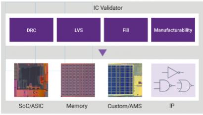
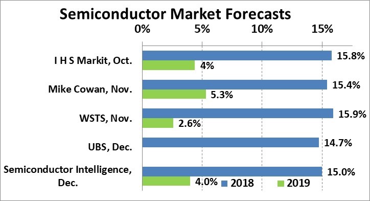
The IC CMP market segment, which can be measured in term of its (chemical) slurries and pads market valuation –the two key consumable CMP components (refer to figure 1), has experienced almost a constant growth over the last decade as shown in figure 2.
Despite of such growth, the recurring challenges to an effective planarization are always there. It might involve a non-consistent pattern density or any post-CMP surface quality defects such as those due to over-etching, dishing (over-polishing) or erosion (photoresist temperature-induced shape degradation) –all of which lead to planarity hotspots. Since all FEOL, MOL and BEOL metal layers are subjected to the CMP processes, the ramification of a subpar surface quality due to these hotspots could compromise the final quality of local devices as well as the overall design.
On the other side of the equation is the mainstream initiative known as design technology co-optimization (DTCO). It has been adopted by many backend design teams embracing advanced process nodes and has been designated as a mediation process –aimed at mitigating both yield and schedule impacts due to any unrealistic or aggressively unproven process assumptions driven by technology scaling need.
As timing and functional simulations have succeeded in addressing pre-tapeout performance and functional risks, performing CMP simulation prior to actual manufacturing would provide early assessment of the process outcomes and de-risk potential yield loss by permitting the application of corrective remedies. A surface profiling by means of modeling and CMP simulation provides ample data for the visualization, analysis and hotspot detection of the design topology and thickness prediction. Since many CMP hotspots originated in design-specific layout issues, proper corrective actions can be taken during the design process such as by applying dummy metal fill, slotting, or redesigning of the cells. Furthermore, design and parameter adjustments can be made to minimize these issues in the subsequent iterations.
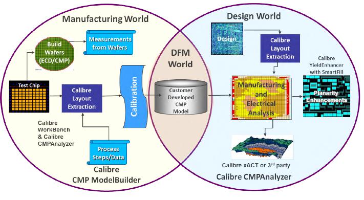
Calibre® CMP ModelBuilder and Calibre CMPAnalyzer tools from Mentor support CMP model building, multi-layer full-chip CMP simulation, and hotspot detection and analysis. One of its customers is SK hynix, the second largest memory semiconductor manufacturer, that deals with the fabrication of DRAM, NAND flash and system IC such as CMOS image sensors. Using Calibre CMP ModelBuilder tool, the design team created a highly accurate CMP model on a testchip and applied measurements from specially design CMP test patterns to generate CMP simulation data that helped predict device damage potentially cause during CMP and to implement subsequent layout optimizations that would prevent or minimize this damage.
The Calibre CMP ModelBuilder tool supports models for the deposition processes and is capable of generating post-deposition profiles for polishing. The Calibre CMP ModelBuilder geometry extraction step calculates pattern density, weighted average width, space, perimeter, and other characteristics for each window, and passes them to the CMP model for simulation. The tool determines local pressure distribution due to surface profile height variation, and local removal rates depending on local pattern geometry and dishing. A time based polishing profile is modeled until the CMP stop condition is satisfied.
The selected process being explored by the team was an oxide CMP step –involving a process stop prior to poly hard mask layer. The CMP model building test mask requires 30-50 test patterns, containing various combinations of line widths and spaces covering the possible structures of the real design.
A subsequent model calibration was done on the model by applying obtained measurements of profile scan data from pre- and post-CMP process for all blocks. This includes the measured erosion, the dishing data and the thickness of cross-section images (refer to figure 3). The CMP dishing, however, was defined in term of device edge-damage and was extracted from measuring the edge damage in cross-section images. The calibration yielded a less than 30A error in dishing prediction for all test blocks as shown in figure 4.
By performing a CMP simulation on post calibrated CMP model, the team was able to predict CMP induced dishing hotspots –prior to the actual mask tapeout and production, preventing a device damage. Using the dishing simulation results, the team was also able to optimize the dummy pattern offset from the main patterns to avoid the predicted device damage.
In a DTCO scenario, foundry engineering could provide the calibrated CMP models and perform the CMP simulation on the designs received for production. Should there be any hotspots, the designs-under-trial can then be retouched by the design team using a list of suggested design optimizations to resolve the predicted post-CMP issues. Such approach yields a significant time and cost saving as it avoids manufacturing failures early.
As key takeaways, newer process nodes driven by emerging applications incorporates increasingly complex surfaces such as 3D structure and new materials. The number of CMP steps also growing in order to enable new process integration. To apply a CMP modeling and simulation in the DTCO process helps prevent the risk of manufacturing induced design failures.
For more details info on Mentor CMP modeling and simulation check HERE