RVN! 26 Banner revised (800 x 100 px) (600 x 100 px)

Alchip moves from TSMC 7nm to 5nm!

Alchip moves from TSMC 7nm to 5nm!
by Daniel Nenni on 08-20-2020 at 10:00 am

Alchip 5nm TSMC

While Alchip is speeding its way down the TSMC process technology roadmap I am reminded how important services are to the semiconductor ecosystem. We can thank ASIC companies like Alchip for the heavy investment systems companies have made into semiconductors. We covered this in our book “Fabless: The Transformation of the Semiconductor Industry” in Chapter 2 The ASIC Business. Today, system companies account for more than half of the spending inside the semiconductor ecosystem so let’s give a round of applause to the ASIC market segment, absolutely.

It has been a very busy month. Last week Alchip announced 5nm capability and next week Alchip will be presenting at the TSMC symposium: “Reticle Size Design and Chiplet Capabilities”. The presentation will cover the all important:

  • N12 Machine Learning Chip Design Achievements
  • Large SoC Design and MCM Chiplet Challenges
  • Alchip’s Large SoC and MCM Chiplet Solutions

And here is the 5nm announcement from last week which includes packaging from TSMC. TSMC certainly loves Alchip:

ALCHIP TECHNOLOGIES OPENS 5NM ASIC DESIGN CAPABILITIES

First Dedicated ASIC company to accept 5nm projects

Milpitas, CA. August 13, 2020 – Alchip Technologies to became the first dedicated ASIC company to announce 5nm commercial design readiness and that is accepting 5nm design. First test-chip tape-outs are expected in December.

Alchip’s complete 5nm design-to-delivery methodology focuses on minimizing design turnaround time. Physical design attributes include a chiplet technology platform, high performance computing IP portfolio, IP sub-system integration services and the latest 2.5D heterogeneous packaging capabilities.

The company expects that 5nm demand will come initially from high-performance cloud computing applications. Still, Alchip expects that 5nm devices will be 52% smaller, 3% faster, yet use only 36% of the power, compared to current 7nm devices.

Alchip 5nm designs will draw upon a high-performance computing IP portfolio that includes “best in class” DDR5, GDDR6, HBM2E, HBM3, D2D, PCIe5, 112G serdes IP from Tier 1 providers. Alchip in-house IP sub-system integration services cover PCIe5, DDR5, HBM2E/3, and 112G PAM4 serdes.

Critical to 5nm production is an innovative advanced packaging capability that is for MCM, CoWoS and InFO_os. Package design covers SIPI/thermal simulation that provides plug-and-play post silicon solutions to reduce substrate layers and the resulting cost. The result is very elegant 5nm devices with more accurate power and thermal estimation flows for high power designs that have avoided post-silicon surprises.

“We’re rolling out our 5nm capabilities now to meet hyper-scalers’ demand that is being driven by the work-from-home, online-everything and business continuity surge trends that are driving significant data traffic and demand-pull for compute workloads,” said Johnny Shen, Alchip President and CEO. “We’ve made a commitment to the market that we would meet the demands of advanced technology head-on and today’s 5nm announcement substantiates that commitment.”

About Alchip
Alchip Technologies Ltd., headquartered in Taipei, Taiwan, is a leading global provider of silicon design and production services for system companies developing complex and high-volume ASICs and SoCs. The company was founded by semiconductor veterans from Silicon Valley and Japan in 2003 and provides faster time-to-market and cost-effective solutions for SoC design at mainstream and advanced, including 7nm processes. Customers include global leaders in AI, HPC/supercomputer, mobile phones, entertainment device, networking equipment and other electronic product categories. Alchip is listed on the Taiwan Stock Exchange (TWSE: 3661) and is a TSMC-certified Value Chain Aggregator.

For more information, please visit our website: http://www.alchip.com

Also Read:

Alchip Delivers Cutting Edge Design Support for Supercomputer Processor

CEO Interview: Johnny Shen of Alchip

Alchip Reveals How to Extend Moore’s Law at TSMC OIP Ecosystem Forum


Major Hardware Security Initiative Adds Tortuga Logic

Major Hardware Security Initiative Adds Tortuga Logic
by Bernard Murphy on 08-20-2020 at 6:00 am

cybersecurity 2 min

You can update ..Generally, I’m a fan of letting market forces figure out best solutions to whatever evolving needs we may have, but I’m enough of a realist to accept that’s not a workable answer to every need. Some problems need a top-down fix. However, we can’t expect policymakers or industry consortia to create compliance demands in a vacuum. Useful regulations can require that we follow a standard only if such a standard has been defined already, ideally by widely respected authorities. This is very much the case for security in modern electronic systems.

Major hardware security initiative

We have isolated islands of standards such as PCI for payment cards, but we need a broader initiative to cover all the billions of potential devices in the extended Internet of Things. In security an authoritative source in this area for quite a while, certainly for software security, has been the MITRE corporation, who developed and maintain the Common Weakness Enumeration (CWE). A related effort, developed by the Department of Homeland Security (DHS) is the Common Attack Pattern Enumeration and Classification (CAPEC). These efforts have now merged under a common board for CWE/CAPEC, sponsored by the DHS and managed by MITRE. Jason Oberg, co-founder and CTO of Tortuga Logic, has been appointed to this newly-announced board.

Mitre CWEs now cover hardware also

MITRE recently extended their security focus to weaknesses and vulnerabilities in hardware (FPGA, ASIC and SoC), driven by input from Intel, with contributions by Tortuga Logic’s security team. In my view this is a much-needed extension, given growing attention to software exploits on hardware weaknesses. Now we have the potential to think of overarching security concerns rather than legacy divisions between methods of implementation. Product development teams will be able to leverage these efforts to secure their devices and Jason will now help set the industry direction for this.

MITRE’s started on CWE in 2006. This now supports a wide range of software security tools., including CAST, IBM, MathWorks, RedHat, Synopsys, and others.  It is reasonable to expect that similar efforts will appear for the hardware aspect. In fact, Tortuga Logic already has an approach to security verification which is very synergistic with these efforts, looking at vulnerabilities very broadly in terms of threat models defined by CIA triad. First confidentiality: privileged information may not leak. Second integrity: no attack may modify such information. Third availability: the system remains resilient even under attack.

Most CWE’s now supported in Radix ruleset

Tortuga Logic has mapped over 83% of the currently listed hardware CWEs into rules for their Radix family of products.  Radix represents these in terms of assets to be protected and other generalized characteristics of a design. For example, assets should not leak through any path to the JTAG boundary. You can update these rules easily to reflect specifics of a given design. Which provides an almost turnkey set of rules reflecting the state-of-art expectations for organizations using hardware CWEs.

I should remind you that the Radix tools build instrumentation to check compliance to these rules. Those checks can run in your normal verification flow. In simulation or in emulation. When I say normal, I mean normal. No need for special security-aware testbenches. Jason tells me that if your verification coverage is good enough for regular signoff, it will also be good enough for security signoff.

Pretty useful, considering who’s standing behind this emerging definition of security. You can read more about Tortuga and their CWE white paper and CWE security HERE.

Note that Andreas Kuehlmann, previously of the Synopsys Software Integrity Group, is now CEO at Tortuga Logic.


Inside a Counterfeit 8086 Processor

Inside a Counterfeit 8086 Processor
by Ken Shirriff on 08-19-2020 at 2:00 pm

Fake Intel 8086 CPU

Intel introduced the 8086 processor in 1978, leading to the x86 architecture in use today. I’m currently reverse-engineering the circuitry of the 8086 so I’ve been purchasing vintage 8086 chips off eBay. One chip I received is shown below. From the outside, it looks like a typical Intel 8086.

The package of the fake 8086. It is labeled as an Intel 8086 from 1978

I opened up the chip and looked at it under the microscope, creating the die photo below. The whitish lines are the metal layer, connecting the chip’s circuitry. Underneath, the silicon has a purple hue. Around the outside of the die, bond wires connect the square pads to the 40 external pins on the IC.

Die photo of the fake 8086, showing the metal layer on top. The thick horizontal and vertical strips provide power and ground, while the other wiring connects the components

I quickly noticed, however, that this wasn’t an 8086 processor but something entirely different! For comparison, look at my die photo of a genuine 8086 below. As you can see, the chips are entirely different and the 8086 is much more complex. Someone had taken a random 40-pin chip and relabeled it as an Intel 8086 processor. The genuine 8086 has various functional blocks visible: the 16-bit registers and ALU on the left, the large microcode ROM in the lower right, and various other blocks of circuitry throughout the chip. (The genuine chip also has a tiny Intel copyright and the 8086 part number in the lower right. Click the image to magnify.) The fake chip above, on the other hand, is an irregular grid of horizontal and vertical wiring, with thicker horizontal and vertical lines for power.

Die photo of a genuine 8086 chip

The ULA or Uncommitted Logic Array

If the chip isn’t an 8086, what is it? I believe the fake chip is an Uncommitted Logic Array, a type of gate array. A gate array is a way of making semi-custom integrated circuits without the expense of a fully-custom design. The idea behind a gate array is that the silicon die has a standard array of transistors that can be wired up to create the desired logic functions. This wiring is done in the chip’s metal layers, which are designed for the customer’s requirements.2 Although a gate array doesn’t provide the flexibility of a fully-custom design, it was considerably cheaper and faster to design.

Ferranti invented the ULA in 1972, claiming that it was the first “to turn the logic array concept into a practical proposition.” A ULA allowed a single LSI chip to replace hundreds or even thousands of gates that otherwise would be implemented in a board full of 7400-series TTL chips. The most well-known users of a ULA are the popular Sinclair ZX 81 and ZX Spectrum home computers.3

A ULA was based on a matrix of identical cells that were wired to form the logic gates. Around the edges of the chip, standardized peripheral cells provided the desired I/O capabilities. The diagram below shows a typical cell in the matrix. The cell contains multiple transistors and resistors, which are mostly unconnected by default. The ULA is customized by creating connections between the components to build a set of logic gates.

Layout and schematic of a ULA matrix cell. From Ferranti Quick Reference Guide

The photo below shows the fake chip with the metal layers removed, revealing the transistor array underneath. Each small green/yellow rectangle is a transistor; there are nearly 1000 of them. Note the repeated pattern of cells in the matrix,1 as well as the different peripheral cells around the outside. The density of transistors is fairly low; the chip has empty columns to provide room to route the metal layer.

Die photo of the fake 8086 showing the underlying silicon. The metal layers were removed for this photo

The fake chip uses bipolar transistors,4 completely different from the NMOS transistors in the 8086 processor. The closeup below shows transistors (the striped rectangles) and the two layers of metal wiring connecting them. (The genuine 8086 only has one metal layer, so the fake chip is probably more recent, from the 1980s.)

A closeup of the fake chip showing transistors

There is no manufacturer printed on the die of the fake chip. The matrix cells don’t look like the Ferranti cells. The photo below shows a ULA built by Plessey, another ULA manufacturer. That die has a smaller transistor matrix than my chip, but the overall structure is roughly similar, so Plessey might be the manufacturer.

A Plessey ULA die. From “Computer Aided Design and New Manufacturing Methods for Electronic Materials”, 1985

The photo below shows another detail of the fake chip. Matrix cells are at the top. The peripheral cell below has much larger transistors for I/O. (There are also resistors in the brownish regions, but they aren’t really visible.) The upper metal layer consists of horizontal wiring, while the lower metal layer is mostly vertical. The thick metal line at the right is for power (or perhaps ground) and is connected to a horizontal power distribution trace at the bottom.

Detail of the fake 8086, showing transistors, resistors, and metal wiring


To summarize, the position of the transistors and resistors in the ULA is fixed. This allows the same underlying silicon wafers to be manufactured for all the customers, keeping volume high and costs low. But by customizing the metal wiring layers, the ULA can be completed to fulfill the logic functions each customer needs.

Conclusions

Why would someone go to all the work of relabeling a $3.80 chip? I guess someone had a stack of old custom ICs with no value. By re-labeling them, they could at least get something for them. It hardly seems worth the effort, but I guess they make up for it in volume. The seller has sold over 215 of these 8086’s, although I don’t know if they were all fake or if I was unlucky. In any case, the seller gave me a prompt refund.

The fake 8086 for sale on eBay


The seller’s feedback (below) shows a lot of complaints about fake chips. Even so, the seller’s feedback is 99.2% positive, so I suspect that there are just a few fake chips mixed in with many types of real chips. It’s also possible that most vintage 8086s are purchased by IC collectors who never test the chip.

Feedback on the seller


I’ve been asked if this chip would actually work as an 8086. Sometimes counterfeiters sell a lower-quality chip in place of the real thing, such as the fake expensive op amps found by Zeptobars. But other times the fake chip is unrelated, such as the vintage bipolar RAM chips that I determined was a Touch-Tone dialer. Since an 8086 has 29,000 MOS transistors but the fake chip has under 1000 bipolar transistors, it’s clear that this chip won’t function as an 8086.

The moral is to always be careful when you’re buying chips, since you never know what you might find. Semiconductor counterfeiting is a big business and I’ve encountered just a tiny piece of it. I plan to write more about reverse-engineering the (real) 8086, so follow me on Twitter at @kenshirriff for updates. I also have an RSS feed.

Notes and references

  1. I think the fake chip has a matrix of 8×12 cells, with each of the large “IXI” patterns composed of four cells. 
  2. At first, a ULA was designed by hand by an engineer drawing the interconnects on paper, but by the 1980s, CAD software automated most of the design and testing. The CAD station below is pretty wild.
    CAD system for designing ULAs at Plessey. From “Computer Aided Design and New Manufacturing Methods for Electronic Materials”, 1985
  3. The book The ZX Spectrum ULA: How to design a microcomputer discusses Ferranti ULAs in detail along with a complete explanation of the ULA in the ZX Spectrum. 
  4. Early ULAs used bipolar transistors, with CMOS circuitry introduced later. Different logic families were supported, depending on the needs of the application. Ferranti’s ULAs had three types of matrix cells: RTL (resistor-transistor logic), CML (current-mode logic), and buffered current-mode logic. Other ULAs supported fast ECL (emitter-coupled logic) or standard TTL (transistor-transistor logic).


White Paper – Mixed Signal Verification for Nanometer SOCs

White Paper – Mixed Signal Verification for Nanometer SOCs
by Tom Simon on 08-19-2020 at 10:00 am

Mixed signal SOCs

The number of touchpoints between analog and digital circuits in high performance SoCs is increasing. This is not a problem because it is possible to implement critical analog blocks directly on nanometer scale digital ICs. However, in many cases digital interfaces or digital feedback circuitry configures these analog blocks to improve their performance. As a result, not only do the interfaces between these blocks need to be functionally correct, they need to perform properly when subjected to stresses and strains that are endemic to analog circuits. With more interactions between digital and analog blocks there comes a greater need to verify the entire design with mixed signal simulation for proper behavior in many scenarios and over lengthy time intervals.

Mentor, a Siemens business, has written a white paper on the topic of high performance and high accuracy mixed signal simulation. The paper is titled “Expanding the Scope of Mixed-Signal Verification With Symphony Mixed-Signal Platform”. It talks about verifying the many sensitive analog blocks used in SoC designs, such as PLLs, SerDes, data converters, high voltage switches, high frequency oversampling DACs, charge pumps, and more. These blocks are subject to noise, and variations in process, temperature and voltage.

Mixed signal simulation offers a way to run at different levels of abstractions to provide a tradeoff between runtime and accuracy. This gives designers quicker ways to check for functional issues such as errors or conflicts in integration of the mixed signal blocks at their interfaces. But the Mentor paper points out that this is only part of the battle. Full verification requires complete analysis of analog behavior over a wide range of operating conditions.

Realistic Analog Behavior

High accuracy SPICE simulation is needed to look at what the paper calls realistic analog behavior, often with repeated runs to account for variation, etc. As you are already aware, Mentor has been assembling quite an impressive suite of analog simulation tools over the years. In 2014 they acquired Berkeley Design Automation which provided the technology for their Analog FastSPICE (AFS). Their acquisition of Solido added advanced Monte Carlo and variation simulation tools. Additionally, Mentor offers advanced digital simulation with Questa. However, by themselves these are not enough to tackle the mixed signal simulation challenges of today.

Combined Simulation

The paper focuses on how Mentor’s Symphony mixed signal simulation platform brings together all these strong simulators and ones from other vendors, as well, to solve the difficult challenges faced by SoC designers. Integration with AFS means that large analog circuits can be accurately simulated to reveal realistic analog behavior.  Digital blocks can be described in Verilog, SystemVerilog, or VHDL and analog blocks can be described at the transistor level in SPICE or Verilog-A.

The real secret sauce in Symphony is the A/D Boundary Element (BE). They come already coded and users can easily configure them through parameters. Users can configure the built-in BEs for each specific instance. There are even supply sensitive BEs that can model behavior as the power rails rise to full power.

Real World Cases

The white paper cites two examples where Symphony can help verify complex circuit operation. The first case is pipeline ADCs, where there are feedback loops that are normally very difficult to verify. In particular they discuss the case where there can be either a dual or single supply. Designers need to tune power on reset circuits so they function properly in either case. The second example they offer involves verifying the auto calibration inside a memory controller. Auto calibration is essential for proper synchronization of the data signal and the corresponding strobe.

Conclusion

The paper makes good reading with regard to these two examples, and the larger issue of how important mixed signal simulation is to the verification of high performance SoCs. The flexibility, usability and performance of Symphony make it a key element in SoC design flows. The full white paper is available for reading through the Mentor website.


CEO Interview: Anna Fontanelli of Monozukuri

CEO Interview: Anna Fontanelli of Monozukuri
by Daniel Nenni on 08-19-2020 at 6:00 am

ANNA

Anna has more than 25 years of expertise in managing complex R&D organizations and programs, giving birth to a number of innovative EDA technologies. She has pioneered the study and development of several generations of IC and package co-design environments and has held senior positions at leading semiconductor and EDA company including STMicroelectronics and Mentor Graphics.

Candidly, I’ve never heard of Monozukuri.  Why are you guys suddenly emerging from stealth mode?
Great question. Since establishing Monozukuri in 2014, we’ve spent all of our time defining and refining our IC/package co-design system technology with a team whose broad experience stretches across system architecture, IC design and IC package design.  The team, including myself, comes from  ST Micro and Mentor. We used this time to really study the challenges.  Rather than bolt something on to an existing tools, we took the time to build a revolutionary new design platform from the ground-up.

Clearly, making promises or prematurely hyping our direction would have been counter-productive until products were fully ready.  So we quietly did the hard work and the result are a product line and a technology platform dedicated to support 3D system co-design

And, most importantly, the products are available for licensing now.

 Why is advanced packaging so important to the future of IC design?
I think the semiconductor industry is transitioning from ‘Moore’s law’ to ‘More than Moor’s law.’  So if designers are going to incorporate more functionality into smaller spaces, they’ll be beyond a single piece of silicon.  The next logical extension is to integrate multiple devices in a commercially-compelling, space-saving wrapper that optimizes system performance.

That what 2.5/3D heterogeneous integration is all about.   Each silicon component can target the ideal PPA manufacturing node.  Expensive latest technology can be reserved for only the most aggressive digital demands, while the remaining  ICs (including a silicon interposer) can target more cost and performance-efficient options.

Advanced AI system, networking products, cell phones, and wearable devices all require highly complex, small form factor systems.   Emerging 2.5/3D packages integrate highly complex multi-chip solution with tens of thousands of connections that support massive, high-speed data in a space-optimized system.

GENIO is your first co-design system.  What are some its features?
GENIO provides a holistic design environment for 2D, 2.5D and 3D multi-component systems. GENIO is actually a suite of tools that generates new levels of performance in terms of speed, optimization efficiency, and system performance.

GENIO generates system design across multiple levels and components including die, chiplet, silicon interposer, package, and PCB.  It’s  proven to eliminate dead end architectures and ensures first-time-silicon success.

The GENIO suite uses standard formats to seamlessly integrate with all existing commercial implementation platforms or dedicated plug-ins to integrate into custom EDA flows.  Its graphic interface provides an immersive 3D interactive visualization of the complete system. GENIO’s architecture also enables new standard and customized features that support both evolving tool environments and proprietary customer-specific requirements.

Which one feature do you believe is absolutely key to the future of  Co-design ?
I believe that true system co-design must be created from concept to completion by including all components from board level to chip level within the same seamless, comprehensive environment.

GENIO allows designers to consider all system components from initial high level system design exploration to detailed system integration and optimization.  This is what enables design across multiple levels and components.

A larger competitor announced that they are working on a co-development tool, yet you’re announcing GENIO is available now.  How did you get to market so quickly?

We’re seeing larger EDA companies racing to address co-design by evolving and adapting existing IC and package design tools.  That approach severely compromises overall systems functionality.

At Monozukuri, we’ve been ahead of the game since 2014.  That’s why today, we’re delivering … and I emphasize delivering …  a ground-up, integrated technology that embraces all of  the demands of  complete 3D system co-design.

We’re able to do this because GENIO is completely unconstrained.  What I mean is that GENIO works with all system components from board to chip because we built it from the ground up. It’s completely agnostic to surrounding EDA tools and it interfaces with almost all IC and package physical design tools.

You keep emphasizing immediate availability. Where’s the data to back that up?
Over the past 12 month we’ve demonstrated GENIO to multiple customers and have run a number of custom optimizations.

For instances, we successfully completed a 2.5D system feasibility analysis in 6 hours that previously took three entire teams … one for architecture, one for backend and one for package … 15 days.  That’s literal a 99.95% reduction in design time, with an associated 99.95% cost savings.

Another customer used GENIO to determine in four hours what a manual solution couldn’t accomplish in two weeks:  Discovering that a proposed IC/packaging system architecture wouldn’t work.

Finally, GENIO optimized a 2.5D HBM-based design that included a complex hierarchical ASIC … multiple hard-IP, plus multiple soft IP, plus probe pads and a complex P&G pins scheme ..  using recursive methodology within 8 hours. While the customer didn’t disclose the cycle time, we believe their traditional methodology would have taken around 45 days.

What’s the roadmap for GENIO?  When can we expect to see a full 3D tool?
Today we have a 2D and 2.5D solutions available.  The 3D platform is in final stage beta testing and is scheduled for release in the 4th quarter.

GENIO 3D includes three features essential for complete system I/O optimization:  First, the ability to manage component placement priority within the 3D stack at the architectural exploration stage. Second, TSV location management to meet manufacturing and/or customer-specific constraints. And last, complete through-stack optimization to minimize TSV population whilst managing system optimization to lessen TSV yield impact .

This is a huge undertaking and you certainly haven’t been on the VC map.  Where did you get your funding?
We financed the company using European and Institutional private equity. Through this funding we were able to complete proof-of-concept and early product development.

However, the majority of funds has come from project grants associated with European research program. Through our participation in the Horizon 2020 program we not only made significant contributions to European research, but also used the findings to complete tool development and get ourselves ready to market.

Where to from here?  When can we expect to hear more from Monozukuri?
Actually, now that we’re negotiating initial licenses, you’ll probably see a great deal of us.  While we were in stealth, we felt it necessary to decline a number of invitations to discuss our technology platform and some of the co-design challenges we all face.  Now, we’re wide open to discussing what we see as the barriers and opportunities along the co-design frontier.  We already shared our short-term roadmap, and we look forward to upholding our role as co-design innovator.

Also Read:

CEO Interview: Isabelle Geday of Magillem

CEO Interview: Ted Tewksbury of Eta Compute

CEO Interview: Ljubisa Bajic of Tenstorrent


The Big Three Weigh in on Emulation Best Practices

The Big Three Weigh in on Emulation Best Practices
by Mike Gianfagna on 08-18-2020 at 10:00 am

Emulation Best Practices

As software content increases in system-on-chip and system-in-package designs, emulation has become a critical enabling technology for the software team. This technology offers software developers the opportunity to verify their code in against a high-fidelity model of the target system that actually executes fast enough to run real application software scenarios. The opportunity for system validation, performance improvement and power reduction with an emulation approach are substantial and often deliver the margin of victory for complex projects. So, the opportunity to hear the big three weigh in on emulation best practices is not to be missed.

Of course, I’m referring to Cadence, Mentor and Synopsys as the big three and they presented at one of SemiWiki’s Best Practices webinars. Hearing the perspective of all three in one webinar is quite a treat. The webinar will be aired on Tuesday, August 25, 2020 from 10:00 AM – 11:00 AM PDT. I highly recommend you register for this webinar.

You will be treated to a series of thoughtful overviews on the topic by some truly world-class speakers. The background on the presenters deserves a bit detail.

Shantanu Ganguly presented for Cadence. He is the lead for the Systems and Verification Group’s product engineering organization. He is responsible for product definition, new technology deployment, and engagement management for all verification technologies. Prior to Cadence, he led emulation and verification applications at Synopsys. He also spent about 11 years at Intel, including work on the ATOM SoC design. He led SoC physical design and tapeout at Qualcomm and was a CAD manager and Sun Microsystems and Motorola Semiconductor. Shantanu  began his career as a consultant at Bell Labs working on layout verification automation. He holds a Bachelor of Technology degree from the Indian Institute of Technology, Kharagpur and a PhD in computer engineering from Syracuse University.

Jean-Marie Brunet presented for Mentor, a Siemens Business. He is the senior marketing director for the Emulation Division. He has been with Mentor for 15 years. Prior to that, he led applications engineering and design services at Silicon Design Systems, was a director of engineering at Micron Technology, director of product development at Music Semiconductors and business development manger at Cadence. His career began at ST. He holds an MS/EE degree from Institut supérieur d’électronique et du numérique.

Melvyn Goveas presented for Synopsys. He is the emulation lead system architect there. Before joining Synopsys, he worked at Intel where he drove emulation and simulation acceleration technology development and application to enable validation shift-left across multiple business groups and helped advance the state-of-the-art in the industry. He holds an MS and BS degree in electrical and computer engineering from the University of Texas at Austin.

With a cast like this, there’s a lot to learn about emulation best practices. I’ll just give you a few highlights from each presentation. You really need to see the webinar for yourself to get the full benefit.

Cadence

Shantanu spent some time discussing the various usage scenarios for emulators. He pointed out there isn’t one platform that is best suited for every scenario. The type of regression or debug you plan to accomplish will influence the configuration and utilization of your platform and the way you handle the data. He gave many example applications and how to approach them. Shantanu then provided the details of an example design flow. He also explored the various components of the Cadence verification platform.

Mentor

Jean-Marie began with an overview of the latest emulation best practices. He touched on topics such as power profiling and analysis under real workloads with real-world examples running during the discussion. He also discussed the strategy and benefits of the Mentor + Siemens autonomous vehicle PAVE360 digital twin program. Jean-Marie also discussed the specific verification needs of 3DICs and how emulation can address those needs.

Synopsys

Melvyn started his presentation with a story about his first emulation project on the first commercial emulator over 30 years ago. Things have clearly changed a lot. He then looked at how emulation has advanced over the years, taking into account the various standards that have influenced the use models. He also discussed the underlying technology used in emulators and how changes there unlocked new opportunities.

The webinar also has some great Q&A sessions. What I’ve presented here is a small portion of the content presented by three very accomplished technologists. As I’ve mentioned, the opportunity to hear the big three weigh in on emulation best practices is not to be missed.

I encourage you to experience the entire event by registering for the webinar here.

Also Read

Cadence Increases Verification Efficiency up to 5X with Xcelium ML

Structural CDC Analysis Signoff? Think Again.

Cadence on Automotive Safety: Without Security, There is no Safety


Interconnect Basics: Wires to Crossbar to NoC

Interconnect Basics: Wires to Crossbar to NoC
by Bernard Murphy on 08-18-2020 at 6:00 am

rats nest min

To many of us, if we ever think about interconnect on an SoC, we may think delay, power consumption, congestion, that sort of thing. All important points from an implementation point of view, but what about the functional and system implications? In the early days, interconnect was very democratic, all wires more or less equal, connecting X to Y wherever needed. If you had a data bus, you’d route that more carefully to ensure roughly equal delays for each bit, which works pretty well when you don’t have a lot of on-chip functions. But there’s more to it than that. This blog is a quick introduction to interconnect basics.

Interconnect Basics: Crossbars

As process sizes shrank, we jammed more functions onto each chip, each handling fatter data busses. This created a lot more connectivity around the chip. Masses of wiring didn’t scale down as fast as the functions. Connecting X to Y wherever needed was no longer practical because, in the ad-hoc approach, the number of connections scales up much more rapidly than the number of functions.

Enter the crossbar switch. Like old-style telephone switches, everyone connects to a central switchboard. But this switchboard can only allow one active call at a time. If X wants to talk to Y, it has to make a request to a central controller – the arbiter, which may be busy handling a conversation between A and B, so X and Y have to wait until that earlier conversation is complete. Still, you no longer need a rats-nest of connections, making the whole thing more scalable, at the expense of becoming more bureaucratic and waiting for your turn in line.

As soon as we see bureaucracy, we want to streamline it. We can have more than one switchboard, so local calls in different regions don’t tie each other up. Then we have separate switchboards for long-distance calls. We can even interleave calls (at least for data). In the Arm AMBA architecture, you can have multiple switches, each with its own protocol supporting different levels of sophistication. But each is still (mostly) a one conversation at a time switch, perhaps with interleaving. This can make it challenging to manage the quality of service, such as guaranteed response times in safety-critical systems. Also, while crossbar switches are way better for managing congestion than ad-hoc wiring, they still can get pretty bulky when they have to support the fat busses we see these days (64 bit or more).

Interconnect Basics: Networks on chip (NoCs)

Which brings me to networks on chip (NoCs). These are inspired by computer networking concepts (though not as complex), with a layered architecture separating physical, transaction and transport layers and using data packetization and routing. Pretty obvious in hindsight. PCI-Express was one early example. Arteris IP introduced the first commercial NoC IP implementation in 2006 and saw rapid adoption in some of the leading SoC vendors because those vendors had no choice but to move to a more effective interconnect to meet their PPA and quality of service goals. (I’m sure in some cases there was also an internal NoC versus purchased NoC debate. Evidence suggests Arteris IP won most of those battles.)

This NoC approach provides obvious advantages over the earlier methods. First, because data is packetized with header data, it’s much easier to control the quality of service through rules. There’s no chance that one communication hog can lock up the whole network until it’s done. You can control protocols for those who get priorities and for how long before the next conversation gets a shot. Similarly, it’s much more scalable than crossbars. Network interface units handle packetization at each IP interface to the network. The network doesn’t bear any of that load, which means that the transport and routing can be very lightweight and fast.

Implementation control

Because the physical layer is separate from transport and transaction, you are free to optimize implementation choices locally (such as using one wire or more than one) to best serve performance needs versus congestion. This is, I think, one of the deal closers for NoCs, something that is next to impossible for crossbar architectures. In a NoC, you can adjust topology locally (between routers) to best manage floorplan needs. Equal deal closers are attainable quality of service with your own transport rules, and ease of timing closure in the Arteris IP architecture because they use a globally asynchronous, locally synchronous (GALS) approach in the network.

NoCs aren’t just for the top-level

I could go on, but I’ll leave you with one more thought. For a while, serious SoC developers thought “OK, we’ll still use crossbars inside our IPs and subsystems, but we’ll use a NoC at the top-level.” Now the NoCs are starting to move inside the subsystems too, particularly as AI accelerators are moving onto these systems. For all the same reasons: networks needing to span huge designs, controllable quality of service, controllable timing closure, etc., etc.

To learn more, here’s a great peer-reviewed Springer paper that describes a real-world example of how to set up quality of service with a NoC, using Arteris IP FlexNoC as the interconnect: “Application Driven Network-on Chip Architecture Exploration & Refinement for a Complex SoC”

Also Read:

Where’s the Value in Next-Gen Cars?

Design in the Time of COVID

AI, Safety and Low Power, Compounding Complexity


SEMICON West – Applied Materials Selective Gap Fill Announcement

SEMICON West – Applied Materials Selective Gap Fill Announcement
by Scotten Jones on 08-17-2020 at 5:00 pm

Applied Materials Selective Gapfill July 2020 Page 02

At SEMICON West, Applied Materials announced a new selective gap fill tool to address the growing resistance issues in interconnect at small dimensions. I had the opportunity to discuss this new tool and the applications for it with Zhebo Chen global product manager in the Metal Deposition Products group at Applied Materials.

The discussion started off with PPACt, Power, Performance, Area, Cost and Time to market. This was also a key theme at the Imec Technology Forum and is of interest to me because as I mentioned in the Imec article my company has a simulation tool to provide process cost and cycle time. You can read my Imec article here.

Figure 1. PPACt.

With EUV entering volume production a key enabler to continued transistor shrinks is now on-line. But the problem is as transistors shrink and provide improved performance shrinking contacts, vias and interconnect lines are seeing increased resistance and that is becoming a bottleneck holding back the transistor gains.

Figure 2. Evolution of Transistor and Interconnect Scaling.

 A key issue is that with existing deposition technologies contacts require liner/barrier layers of high resistivity material and liner/barrier thicknesses are not scaling down. The result is the volume of actual conductor for small contacts is being squeezed down, for example at 7nm for a 20nm contact only about 25% of the volume is tungsten conductor (W). The current conformal deposition technologies also leaves a seam/gap in the middle of the contact.

Figure 3. Contact Scaling Paradox.

 What Applied Materials has developed is a multi-process platform that provides bottoms-up, selective, seam-free gap fill. This set of technologies can fill a contact or via from the bottom up, selectively so it only fills over metal – where there are gaps in the dielectric layer and does not require a barrier/liner. The result is a contact or via that is 100% conductor metal providing lower resistance.

The new Volta Selective W CVD system runs on the proven Endura platform and combines a metal surface treatment, a dielectric surface treatment and a selective W deposition on a single tool.

Because there are no seams the grains size is larger reducing grain boundary scattering – reducing the resistivity of the W. For a 35nm slot contact a 40% reduction in resistance is seen. Smaller contacts see even bigger resistance reductions.

Figure 4. Selective Fill Advantage.

This process is targeting vias because it only deposits over metal.

Applied Materials is getting strong traction on the new system and has already shipped >20 Volta Selective W systems to leading foundries worldwide.

This is a solution to a key problem that is growing in importance.

Also Read:

Imec Technology Forum and ASML

VLSI Symposium 2020 – Imec Buried Power Rail

Key Semiconductor Conferences go Virtual


A “Super” Technology Mid-life Kicker for Intel

A “Super” Technology Mid-life Kicker for Intel
by Tom Dillinger on 08-17-2020 at 10:00 am

TigerLake WillowCove

Summary
At the recent Intel Architecture Day 2020 symposium, a number of technology enhancements to the Intel 10nm process node were introduced.  The cumulative effect of these enhancements would provide designs with a performance boost (at iso-power) approaching 20% – a significant intra-node enhancement, to be sure.  The initial release of CPUs in this 10nm “SuperFin” process is scheduled for this Fall, as part of the 11th-Generation TigerLake mobile client product family announcement, based on the WillowCove core.  (The Sapphire Rapids Xeon server processor on an enhanced SuperFin process will ship in 2H21.)

Figure 1.  Performance boost for the WillowCove core, and a TigerLake SoC block diagram.

Background

CPI for Yield
After a process technology reaches production volume qualification status (“v1.0”), fabrication engineers remain focused on continuous process improvement (CPI).  These ongoing improvements span a wide range of areas, from additional materials quality inspections to photolithography exposure window optimizations to (deposition and/or etch) equipment updates.  Collectively, these new manufacturing steps fall under the broad heading of statistical process control (SPC).   The goal of this CPI effort is to improve fabrication yield, from both defect density reductions and reducing the (3-sigma) performance variation endpoints.

Figure 2.  Illustration of the overall (Gaussian) performance distribution, and the common “3-sigma” WC/BC design targets.

The transition to a new CPI-driven process variant is typically done with the encouragement of the foundry’s customers, as yield is improved, although some customers may wish to review the engineering updates with the foundry to assess any product re-qualification requirements.  A key characteristic of this CPI effort is that no (major) lithography design rule modifications are introduced – only an assessment of the need for re-analysis of electrical characteristics and/or post-silicon re-qualification.

A Process Node “Kicker”
There is another class of CPI-based enhancements, commonly known as a mid-life kicker.  After customer parts are shipping in volume, a more significant set of process enhancements may be available, potentially including lithography design rule updates.  A long-life, high-volume product might be a candidate for the engineering investment to re-target an existing design to the new process variant, to offer a product mid-life “kick” to the performance specifications.

In the era of Dennard scaling for CMOS technology, these mid-life process variants were commonly associated with the introduction of a half-node, typically a broadly-applied 90% “shrink” of the photolithographic design rules.  Ideally, most of the physical lithography design rules supported this 0.9X multiplier, leveraging the capability to adjust the mask aligner’s optical reduction ratio for the mask-to-photoresist focal length.  The intent was to minimize the need for physical design changes, re-using masks whenever possible.  Existing designs would be shrunk and re-analyzed for electrical integrity.  (I/O cells, mixed-signal circuits, and SRAM arrays required more focus than digital library cell-based blocks.)  Thus, the evolution of 0.5um à 0.45um through 90nm à 80nm half-node process introduction and product lifetime extension was a common occurrence.

Process Node Extensions
The era of half-node scaling ended with the introduction of several new process innovations:

  • damascene-based Cu interconnect and via patterning (with trench liners)
  • aggressive optical-proximity correction algorithms on mask data, and forbidden pitch design rules (extending the life of 193nm wavelength exposure, with immersion)
  • sophisticated dummy insertion and fill algorithms (for litho and CMP uniformity)
  • multi-patterning mask data decomposition (to enable ongoing pitch reduction with 193i exposure)

As a result, the CPI engineering team focused on material improvements and deposition/etch enhancements to the baseline process, and (potential) physical design rule updates that would offer a performance boost.   The common nomenclature was to refer to this new process extension as the “plus” version at the existing node.  (Indeed, successive process variants kept adding plus signs.)

Unlike the half-node shrink of an existing design, these enhanced process variants would require significant physical design re-implementation to realize the available performance gains – e.g., block re-composition using new cell libraries, new SRAM array generation.  For new designs, an evaluation of the performance, power, area, cost, and reliability for the baseline versus “+” and “++” offerings would be used for process selection.

FinFETs and CPI
The introduction of FinFET devices (initially with Intel’s 22nm process) has led to a myriad of CPI opportunities.  As illustrated below, engineering focus has been applied to realize a fin profile with more vertical sidewalls, for improved electrostatic control of the gate-to-fin channel.

Figure 3.  Illustration of the evolution of the FinFET channel profile.

The raised source/drain epitaxial growth regions influence the transistor behavior in multiple ways:

  • high concentration impurity introduction for reduced Rs and Rd
  • transfer of (compressive or tensile) material stress to the channel region, influencing the free carrier mobility
  • an increased gate-to-source/drain parasitic capacitance

The figure below illustrates the additional parasitic capacitances (Cgs, Cgd, and Cgx) due to the three-dimensional geometry of the gate traversal over multiple device fins.

Figure 4.  There are unique parasitic capacitances due to the FinFET geometry.  The raised S/D epitaxial regions (with M0 interconnect) add to the Cgs and Cgd parasitics.

At each FinFET process node, all foundries have introduced “plus” versions for improved performance.

Intel’s 10nm “SuperFin” process announcement
At the recent Intel Architecture Day, a major kicker to Intel’s 10nm process was introduced.

The Intel presentation initially highlighted the process advancements that were incorporated into the baseline 10nm process, as illustrated below.

Figure 5.  Intel 10nm baseline process enhancements

There were acknowledgements from the presenters that the goals for 10nm process scaling were extremely aggressive, and these corresponding process enhancements took longer than originally planned to reach production yield status.

The new 10nm process variant includes several CPI characteristics:

(1)  reduced damascene liner thickness
As illustrated in the figure below, a liner material (of higher resistivity) is deposited on the damascene trench prior to metal deposition for improved adherence.   Reducing the requisite liner thickness reduces the effective resistance, thus reducing the total interconnect R*C delay.

Figure 6.  Damascene-based interconnect and via cross-section, utilizing a liner material

(2)  new epitaxial S/D growth process
An enhancement to the raised S/D growth process step results in greater material stress in the fin channel, enhancing carrier mobility, and thus device current.

Figure 7.  Illustration of the raised S/D epitaxial grown on the S/D sides of the FinFET gate

(3)  physical design rule update to support increased gate-to-gate spacing
It may seem counterintuitive that increasing the device gate pitch in circuit layouts would result in a performance improvement.  Yet, referring to the FinFET parasitic capacitance figure above, the parasitics are an intricate combination of Cgs, Cgd, Cgx, Csx, Cdx, Rs, and Rd, which depend on both 2D and 3D topologies.  (Rgate has already been improved from the introduction of contact-over-active-gate design support.)

When combined with the new raised S/D epitaxial growth and channel stress enhancements, a greater gate pitch could certainly result in better performance.

(4) improved MIM capacitor structure
A significant decoupling capacitance must be connected to the power distribution network (PDN), to reduce power supply rail transients when large switching currents are required.  The total decoupling is a composite of both external capacitance (e.g., surface-mount caps on the package), and die-internal capacitance.  The internal capacitance consists of the “intrinsic” capacitance of the PDN interconnect (and junction nodes) and the “explicit” decoupling integrated into the design.  The explicit capacitance is provided by decoupling cells and a unique metal-insulator-metal (MIM) parallel-plate structure incorporated into the BEOL metallization stack.

Figure 8.  Decoupling library cell and MIM capacitance structure

Figure 9.  Illustration of the MIM addition to the BEOL

Intel announced an enhancement to the MIM structure in 10nm, providing “5X” improved areal decoupling density.

Although the larger logic gate pitch reduces the die area available for decap cells, the increased MIM capacitance density more than compensates.  Indeed, by reducing supply voltage droop, Intel is realizing a net performance gain.

A Cumulative Performance Boost approaching 20%
As was shown in Figure 1, the cumulative performance effect of these 10nm improvements approaches 20% (@ iso-power).  The figure below illustrates the typical Ion versus Ioff comparison curves for successive process nodes – the horizontal line depicts the Ion (performance) gain at the same Ioff (leakage power) for a reference device in the two nodes.

Figure 10.  Typical illustration of the Ion versus Ioff curves for two process nodes

The ~20% performance improvement represents the typical gain between successive nodes – realizing this gain as an extension to the 10nm node is a very significant CPI announcement.

The marketing team at Intel has designated this process variant as “10SF”, where SF is short for “SuperFin”.  An anecdotal comment was made by one of the presenters, “There were already so many process ‘+’ versions for 10nm, it was getting hard to keep them straight – a new naming convention was needed.

Intel will be releasing their TigerLake mobile client processor family this Fall, using the 10SF technology.  It will be extremely interesting to see how the TigerLake PPA compares to other product implementations.

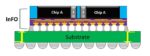
For more information on the Intel Architecture Day announcements, please follow this link.  A wealth of presentation videos and materials are available, covering not only the 10SF announcement, but also the latest CPU and GPU architectures, the FPGA roadmap, (2.5D and 3D) packaging technology highlights, and advanced interconnect strategies.

Sources:
Figures 1, 3, 5, 7, 9:   Intel
Figures 2, 4, 6, 8, 10:  T. Dillinger, VLSI Design Methodology Development

-chipguy


Intel 10nm SuperFin Technology!

Intel 10nm SuperFin Technology!
by Daniel Nenni on 08-17-2020 at 6:00 am

Refining FinFet Intel SuperFin

I made it through the Virtual Intel Architecture Day last week and much to my surprise it was very well done. Virtual events have been hit and miss but this one was definitely a hit. Great content, approachable experts, a glitch-free experience. The mainstream media has been redundantly covering it so let me add my many years of experience, observation, and opinion because that is what a real semiconductor blogger does, absolutely.

I have asked Scott Jones and Tom Dillinger to blog it as well.

Intel announced the NEW 10nm SuperFin technology with NEW SuperMIM capacitors. I warned Intel about making up semiconductor technology words back when they introduced 22nm and called it TriGate technology versus the industry standard FinFET. As history has shown, if you don’t play nice in the ecosystem the ecosystem will not play nice with you.

Tom Dillinger did a more technical blog on SuperFins here:

A “Super” Technology Mid-life Kicker for Intel


The SuperFin technology is replacing the Intel ++++ process naming and is billed as a full process node transition. While I do applaud Intel for getting rid of the ++++ process naming, switching to made up technology names is not the answer.

One of the best process node naming lessons was when TSMC first came out with FinFETs. The Intel 14nm process was more dense than TSMC’s so out of respect for Intel TSMC went with 16nm. Samsung chose 14nm even though their density was comparable to TSMCs. The end result was TSMC having to explain to customers why their 16nm process was actually better than Samsung’s 14nm. TSMC and Samsung are now in lock step on process node naming with 10nm, 7nm, 5nm, 4nm, and 3nm with comparable densities. Intel could save themselves a lot of time and trouble by playing nice in the ecosystem and following this new industry standard naming.

“Intel’s recent announcement of a delay to its 7nm node sent shockwaves through the tech industry…” NOT!

Another experience, observation, and opinion I have is about the 7nm process delay. Let me make this perfectly clear, process delays for IDMs are very common in the semiconductor industry and Intel is no different. Intel 14nm was delayed, Intel 10nm was delayed, so what is the big surprise with 7nm being delayed? Samsung is in the same boat. In fact, one of the reason’s why Apple left Samsung for TSMC was process delays (Samsung 28nm was VERY late so Apple jumped to TSMC for 20nm). Samsung 10nm, 7nm, and 5nm also experienced high volume production delays. Anybody with a modicum of semiconductor experience knows this to be true.

TSMC also experienced process delays before Apple came along. Anybody here remember 1.3m? How about 40nm? Today TSMC does the Apple two-step delivering new processes every year without fail for the annual iProduct Fall rollout.

And don’t even get me started with the whole “Intel going Fabless” headlines. If anything, the Intel Architecture Day made one thing perfectly clear: Intel will be making their own CPUs until the end of time, absolutely. There is hardly a doubt that Intel placed an order for TSMC wafers because Intel has always been a big customer of TSMC through acquisitions. In fact, most if not all, of the chip acquisitions Intel has made have been TSMC customers. Some of the chips move to Intel manufacturing but some do not. For example, low cost and low power chips (Mobileye) will probably stay at TSMC, my opinion.

Intel DID however announce that they are manufacturing a gaming focused GPU outside of Intel fabs (for the first time) to compete directly with AMD and NVIDIA. Intel did not say which outside fab they are using but since Intel is already a TSMC customer that is a pretty big clue. Also, AMD and NVIDIA both use TSMC so it would be an unnecessary risk for Intel to use yield challenged Samsung. Mystery solved!