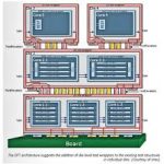
The launch from Cadence of the PCI Express 3.0 Controller IP was officially done about one year ago, and demonstrated at the June 2011 PCI-SIG Developer’s Conference, where Cadence Design IP for PCI Express 3.0 controller IP implemented as a high-performance, dual-mode, 128-bit data-path, x8 PCI Express 3.0 controller configuration was shown, implemented in a customer’s ASIC, see here.
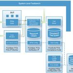
The associated Verification IP (VIP), made of Compliance Management System (CMS) which provides interactive, graphical analysis of coverage results, and PureSuite which provides the PCIe associated test cases, clearly demonstrate that the acquisition of Denali has greatly helped Cadence to position on the advanced PCIe IP market, with design IP (Controller) and VIP.
Maybe some history will help. Back in 2006, Denali was known for their VIP products for Interface functions like PCIe, USB or SATA, when they first launch a PCI Express (gen-1 at that time) Controller IP. It was quite surprising, especially for their former partners, suddenly becoming their competitors! Nevertheless, they found a place on the market, positioning on the high end (and expensive) side, supporting Root Port and soon Single Root I/O Virtualization (SRIOV), a solution targeting the PC Server market when Synopsys and PLDA where positioned on the mainstream PCIe IP market. Then PCIe 2.0 specification was issued, in 2007, and Denali was still in the race. With the launch of this PCIe 3.0 solution, supporting single root I/O virtualization (SR I/OV), Cadence was initially targeting the high end, advanced applications, like storage, supercomputing, enterprise and networking. But, with the release from Intel of the Z68 chipset, PCIe gen-3 ready, in May 2011 and the launch from the motherboard manufacturers (ASUS, ASRock…) of products based on the Z68 chipset, the 3[SUP]rd[/SUP] generation of PCI Express is now available on products sold on the mainstream market.
Initially, Denali was positioning their PCIe Controller IP on the high end and high price market only, leaving the mainstream to the competition. With PCIe gen-3 becoming the solution for the mainstream market, Cadence should increase their market share in the PCIe Controller IP mainstream market and consolidate their share in the high end, thanks to the support of SR-IOV. What is SR-IOV? Briefly, SR-IOV is a specification that allows a PCIe device to appear to be multiple separate physical PCIe devices. PCI-SIG created and maintains the SR-IOV specification with the goal of having a standard specification to help promote interoperability. One of the milestones achieved for Cadence’s design IP for PCI Express Gen3 is proving SR-IOV interoperability in silicon against an Intel chipset.
Why is it important? The two main advantages of an SR-IOV PCIe device are:
- It allows multiple OS’s to have their own private view of the PCIe device
- It helps improve I/O performance by reducing latency of the hypervisor
You will find more information about SR-IOV, as well as a nice video showing how have Cadence customers used PCI Express Gen3 SR-IOV to solve their design problems here.
The PCIe core includes these features:
Single-Root I/O Virtualization
The PCIe core provides a Gen 3 16-lane architecture in full support of the latest Address Translation Service (ATS) specification, Single-Root I/O Virtualization (SR-IOV) specification, including Internal Error Reporting, ID Based Ordering, TLP Processing Hints (TPH), Optimized Buffer Flush/Fill (OBFF), Atomic Operations, Re-Sizable BAR, Extended TAG Enable, Dynamic Power Allocation (DPA, and Latency Tolerance Reporting (LTR). SR-IOV is an optional capability that can be used with PCIe 1.1, 2.0, and 3.0 configurations.
Dual-mode operation
Each instance of the core can be configured as an Endpoint (EP) or Root Complex (RC).
Power management
The core supports PCIe link power states L0, L0s and L1 with only the main power. With auxiliary power, it can support L2 and L3 states.
Interrupt support
The core supports all the three options for implementing interrupts in a PCIe device: Legacy, MSI and MSIx modes. In the Legacy mode, it communicates the assertion and de-assertion of interrupt conditions on the link using Assert and De-assert messages. In the MSI mode, the core signals interrupts by sending MSI messages upon the occurrence of interrupt conditions. In this mode, the core supports up to 32 interrupt vectors per function, with per-vector masking. Finally, in the MSI-X mode, the controller supports up to 2048 distinct interrupt vectors per function with per-vector masking.
Credit Management
The core performs all the link-layer credit management functions defined in the PCIe specifications. All credit parameters are configurable.
Configurable Flow-Control Updates
The core allows flow control updates from its receive side to be scheduled in a flexible manner, thus enabling the user to make tradeoffs between credit update frequency and its bandwidth overhead. Configurable registers control the scheduling of flow-control update DLLPs.
Replay Buffer
The Controller IP incorporates fully configurable link-layer reply buffers for each link designed for low latency and area. The core can maintain replay state for a configurable number of outstanding packets.
Host Interface
The datapath on the host interface is configurable to be 32, 64, 128 or 256-bits. It may be AXI or Host Application Layer (HAL) interface.
Offering the PCIe 3.0 IP Controller and VIP is a must, as Cadence is clearly and strongly positioned on Verification IP and well positioned on a few interface IP, essential to support SoC design, like DDR3, DDR4, LPDDR2, LPDDR3, and PCIe. Several design-in for PCIe gen-3, like those at PMC-Sierra, Cray Research or Marvell have demonstrated that Cadence commitment to the PCI Express market has lead to success. Cadence has enhanced the memory controller products inherited from Denali by moving to a hard PHY solution, will they consolidate their penetration in the PCIe IP market the same way, by adding PHY IP to their port-folio?
By Eric Esteve from IPNEST