
Memory designers need to predict the timing, current and power of their designs with high accuracy before tape-out to ensure that all the design goals will be met. Extracting the parasitic values from the IC layout and then running circuit simulation is a trusted methodology however the accuracy of the results ultimately depend on the accuracy of the extraction process.
Here’s a summary of extraction techniques:
| Extraction | Benefits | Issues |
| Rule-based | High capacity | Limited accuracy, 10% error total capacitance, 15% error coupling capacitance |
| Reference-level solver | High accuracy | Limited capacity, long run times |
| Fast 3D Solver | High accuracy, fast run times | New approach |
Bit Cell Design
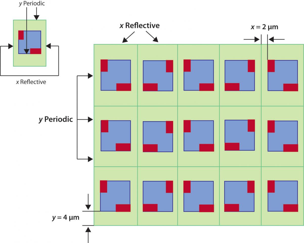
Consider how a memory bit cell is placed into rows and columns using reflection about the X and Y axis:

The green regions are an application of boundary conditions on a cell with reflective boundary enclosed by 2um in the X direction and 4um in the Y direction.
For attofarad accuracy the field solver has to extract the bit cell in the context of its surroundings.
Mentor Graphics has a fast 3D field solver called Calibre xACT 3D that can extract a memory bit cell in just 4 seconds using this boundary condition apprach, compared to a reference-level solver that requires 2.15 hours. I’ve blogged about xACT 3D before.
Accuracy Comparisons
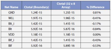
A memory bit cell was placed and reflected in an array, then the entire array was extracted. The unit bit cell used boundary conditions as shown above and the results were compared against an actual array. The accuracy of the boundary condition approach in Calibre xACT 3D is within 1% of the reference-level field solver.
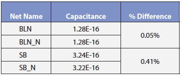
Another comparison was made for symmetric bit lines in a memory array using the boundary condition approach versus the reference-level field solver, with an accuracy difference within 0.5%.
Beyond the Bit Cell
So we’ve seen that Calibre xACT 3D is fast and accurate with memory bit cells, but how about on the rest of the memory like the decoders, and the paths to the chip inputs and outputs?
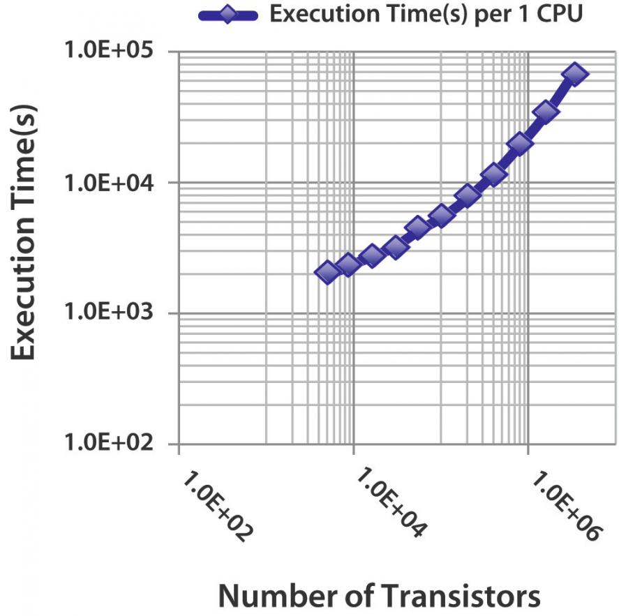
With multiple processors you can now accurately and quickly extract up to 10 million transistors in about one day:
Summary
Memory designers can extract a highly accurate parasitic netlist on multi-million transistor circuits for use in SPICE circuit simulation. Run times with this fast 3D field solver are acceptable and accuracy compares within 1% of reference-level solvers.
For more details see the complete white paper.
Share this post via:


Comments
There are no comments yet.
You must register or log in to view/post comments.