
Anybody who has done any bus & board system design knows the problem. Merchant boards typically have standardized pinouts (after years of haggling in standards organizations) for the backplane bus, and a group of user-defined pins for daughtercard I/O. Homegrown systems usually have a just-as-carefully defined proprietary backplane bus pinout. Once defined, changing a signal name or pin location requires an act of deity.
Or a mistake. Each board design team starts with the pinout table, or if they are lucky they get a connector model in a PWB design tool library. When systems were small, and there were fewer than 20 boards on a backplane, checking interconnects wasn’t too terrible. Every once in a while, someone would miss a pin, or transpose the direction of high-to-low order bits on a parallel signal group. Hopefully that was caught before the smoke test. The offending “odd-man-out” board would be sent back for cut and jump rework, and a revision scheduled.
Systems have gotten huge; in many cases, they are now systems-of-systems. It isn’t unusual to see hundreds of boards with tens of thousands of interconnects including backplane traces, backplane cabling (usually for the user-defined pins), and over-the-top cabling. Boards and cables are parceled out to separate teams, along with some control documents – typically an Excel spreadsheet with the signal tables, or maybe dumb graphics in Visio. The entire system relies on everyone reading the documentation and interpreting it correctly.
 The risk of a disconnect somewhere in the system is also huge.
Not to mention there is little (ok, no) ability to do trade-off analysis. Mentor Graphics released the last update to Xpedition with the ability to optimize pins from the board through the IC package – but what happens if that optimization would benefit neighboring boards? That is a very hard change to drive given semi-manual methods such as Excel or Visio.
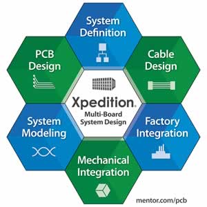
Dave Wiens, Xpedition Product Manager in the Board Systems Division at Mentor Graphics, sums this up as the contrast between the norm of split & fragment design and managed system-of-systems design. He’s been pursuing a new release of Xpedition for multi-board system design with several goals. Rather than holding projects together with desktop office tools, teams can collaborate on “correct by construction” system design.
Reentering data becomes a thing of the past, and design rules can easily check connectivity across boards, backplanes, and cables, eliminating errors. Change management is built-in with controlled synchronization; users also have the capability to accept or reject changes. Disparate teams on large projects that might talk to each other infrequently have fewer worries about the currency of their design information.
One of the more challenging topics in systems design is thermal verification. Instead of the conservative “rule of thumb”, a multi-board system can actually be modeled in this release of Xpedition with confidence, and recommended changes can be driven across boards quickly. The same goes for signal integrity or mechanical issues.
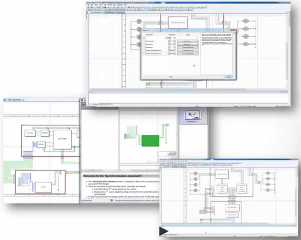
The strength of Xpedition is its underlying data management infrastructure. This is really about a single design flow for all boards, backplanes, and cables, with everyone working in the same project repository with the same tools. Weeks of manual synchronization are reduced to automation, complete with tips and color coding. Cables can be created in schematic form, then optimized for size and weight using 3D modeling.
Much more detail on this announcement is in the Mentor press release:
Wiens says he completely understands existing processes are in place, especially on the change management front. He hopes that as users adopt the new Xpedition release, over time older system-of-systems design approaches yield to the increased efficiency of automation. The new ideas have been shaped with the help of lead customers such as ASML, factoring in a wealth of real-world experience. Any customer designing systems with boards, backplanes, and cables should benefit.
Share this post via:


Comments
There are no comments yet.
You must register or log in to view/post comments.