





Two timing tools that agree can still both be wrong. A small testcase where you can re-derive every printed digit by hand shows that the engine is correct, and when it isn’t, it shows which term is wrong.
By Dr. Sameer Pawanekar, Founder & CEO, Ramtera Inc.
The problem: agreement is not correctness
New static timing engines, and new releases of old ones, are usually validated the same way. You run a set of designs through the new engine and through an established one, plot one slack against the other, and look at the scatter. If the points sit on the diagonal, the engine ships.
Correlation is useful, but it only proves agreement. A correlation run takes on the reference tool’s approximations and bugs. When the two tools disagree, it can’t tell you which one is right. A difference on one endpoint could come from a table lookup, a wire model, a clock edge or an exception one tool ignored. Nor can it catch an error both tools share.
Our timing work for PRE, Ramtera’s place-and-route engine, follows a simple rule: correctness is proven first on testcases small enough that every number in the timing report can be re-derived with a calculator. Correlation on larger designs comes after that and tests the modelling, never the arithmetic. If a digit in the report can’t be re-derived, that is a bug by definition.
The approach: a design you can hold in your head
The golden testcase is deliberately tiny:
- A two-cell library whose delay tables have a single row, so each lookup is a linear interpolation along one axis.
- A four-instance netlist with one register, so the paths can be listed by hand.
- Parasitics simple enough to evaluate manually, with a few resistors and node capacitances per net.
For each reported path, we independently re-derive three classes of number:
- Cell arc delays. Interpolate the library table at the exact load the engine reports.
- Wire delays. Apply the first-moment (Elmore) formula to the RC network. Each sink’s delay is the sum, over the resistors on its path from the driver, of resistance times the capacitance downstream of that resistor.
- Required times. Use the clock period, external input and output delays, margins, and any timing-exception arithmetic.
The engine passes only if it reproduces every printed digit. “Close” is a failure.
Results: one path, every digit accounted for
Here are the key report lines for the worst path in our worked example, with a 0.8 ns clock.
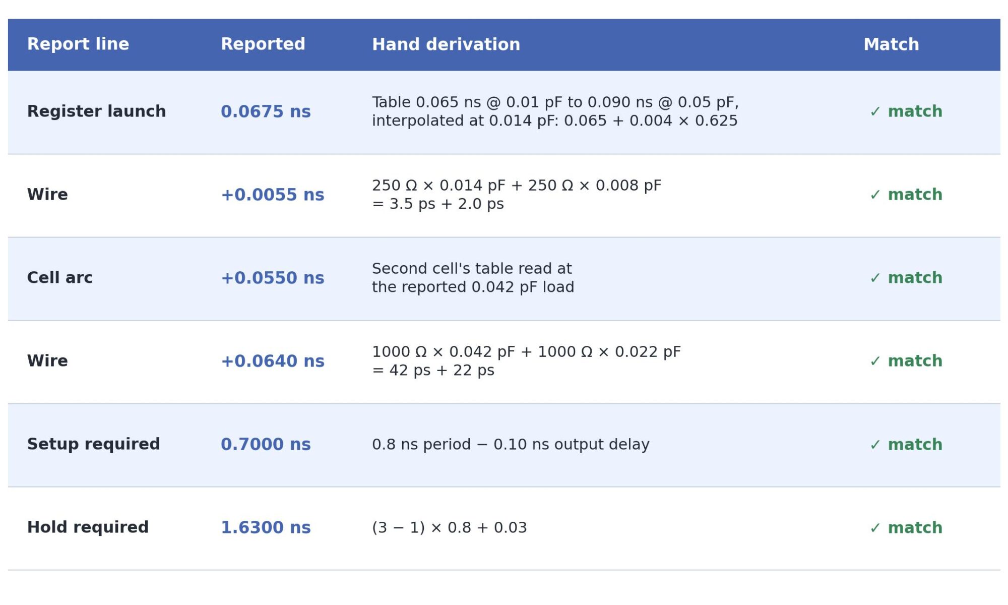
The register launch is reported as 0.0675 ns. The register’s delay table runs from 0.065 ns at 0.01 pF to 0.090 ns at 0.05 pF. The slope is 0.025 ns / 0.04 pF, and the engine reports a 0.014 pF load, 0.004 pF above the first table point. So the delay is 0.065 + 0.004 × 0.625 = 0.0675 ns, which matches.
The next wire is reported as +0.0055 ns. The first-moment sum is 250 Ω × 0.014 pF + 250 Ω × 0.008 pF = 3.5 ps + 2.0 ps = 5.5 ps. (One ohm times one picofarad is one picosecond, which makes these checks easy.)
The next cell arc is reported as +0.0550 ns. That is the second cell’s table read at its reported 0.042 pF load.
The wire after it is reported as +0.0640 ns: 1000 Ω × 0.042 pF + 1000 Ω × 0.022 pF = 42 ps + 22 ps.
The setup required time at the output is 0.7000 ns, the 0.8 ns period minus the 0.10 ns output delay.
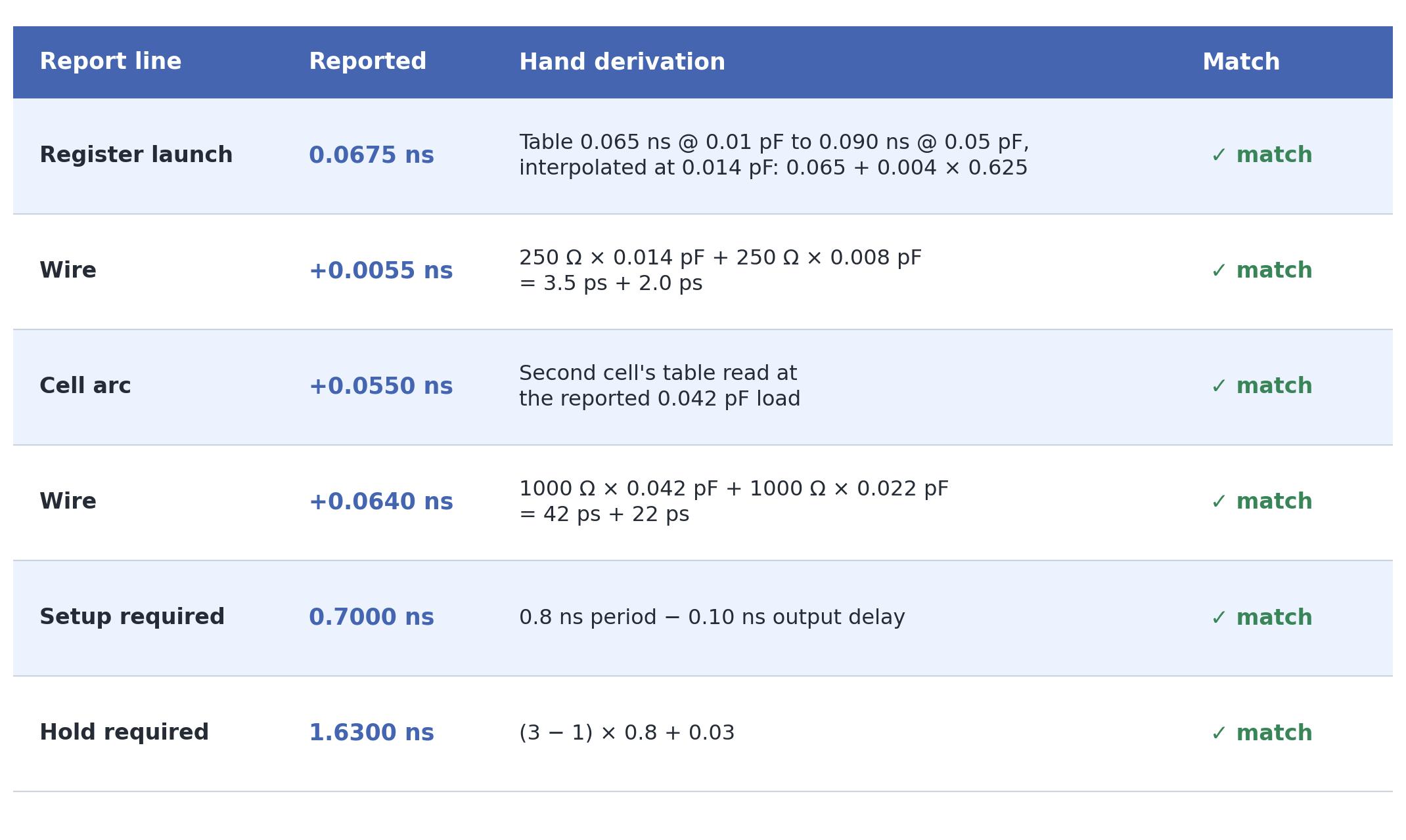
In our worked example, every report line matches its hand derivation, including the hold check. The test covers setup and hold checks and four constraint mechanisms, and leaves no digit unexplained. A mismatch points straight at the lookup, the wire or the required-time term.
Exceptions: test the semantics against documented examples
Arithmetic is the easy part. Timing tools disagree most quietly on path exceptions: false paths, multicycle paths and maximum/minimum delay constraints. When several exceptions match one path, the documented SDC priority model decides which one wins:
- False path beats max/min delay, which beats multicycle.
- Within a class, the exception that names more of -from/-through/-to wins.
- After that, -from outranks -to, and -to outranks -through.
- Pin-based selectors outrank clock-based ones.
- Ties go to the most constraining adjustment.
- An exception with identical selectors overwrites the earlier one.
The golden-testcase discipline carries over directly. The rules come with worked examples in the documentation, and each one is a ready-made testcase with a known answer. Our implementation reproduces 8 of 8 documented example pairs. These include multicycle -from A 3 against -to C 2, where 3 applies because -from outranks -to, and a min-delay that must apply only to hold analysis.
The end-to-end arithmetic can be checked with a calculator too, on the same 0.8 ns design. A 0.30 ns max-delay to an output port gives a required time of exactly 0.2000 ns (0.30 minus the 0.10 ns external delay). A setup multicycle on the same endpoint is reported as ignored because the max-delay outranks it, as the priority rules require. A setup multicycle of 3 with no hold multicycle moves the hold check to (N − 1) cycles, so the required time is (3 − 1) × 0.8 + 0.03 = 1.6300 ns, as in the worked example.
Parasitics: SPEF answers to 0.1 ps
Post-route timing is only as good as the parasitics feeding it. A SPEF (IEEE 1481) reader has a lot of room for subtle errors: unit multipliers, name maps, divider characters, corner triplets and multi-file stitching. The same approach applies. Write a SPEF small enough to evaluate on paper and require the engine to match.
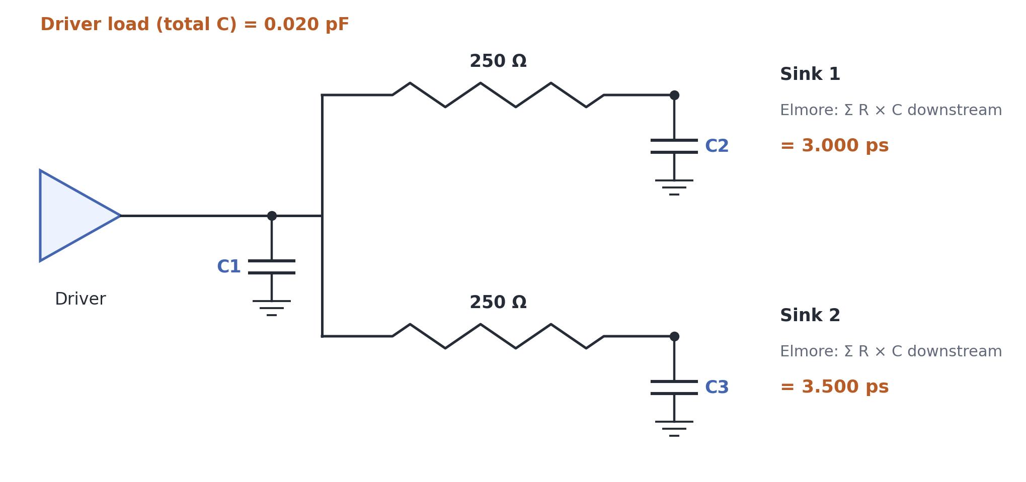
Our reference is a two-sink RC tree with 250 Ω branches and known node capacitances. It must give Elmore delays of exactly 3.000 ps and 3.500 ps and a driver load of 0.020 pF. The engine reproduces all three to the displayed precision, and agrees with hand computation to 0.1 ps. A variant checks the corner handling. Selecting the second field of the corner triplets, where one resistor carries 999 Ω, must move the first sink to exactly 6.995 ps.
The test also checks partial annotation. Nets missing from the SPEF fall back to an estimated wire model, and the analysis banner reports the annotation ratio, for example 4 of 6 nets annotated.
Multi-corner, multi-host: accept only exact equality
Multi-mode, multi-corner analysis multiplies runtime by the number of views, so the usual remedy is to spread the views across hosts. The question that matters is whether the distributed answer equals the local one. The acceptance criterion should be exact equality, field by field. It must also be tested on a case that cannot pass by accident.
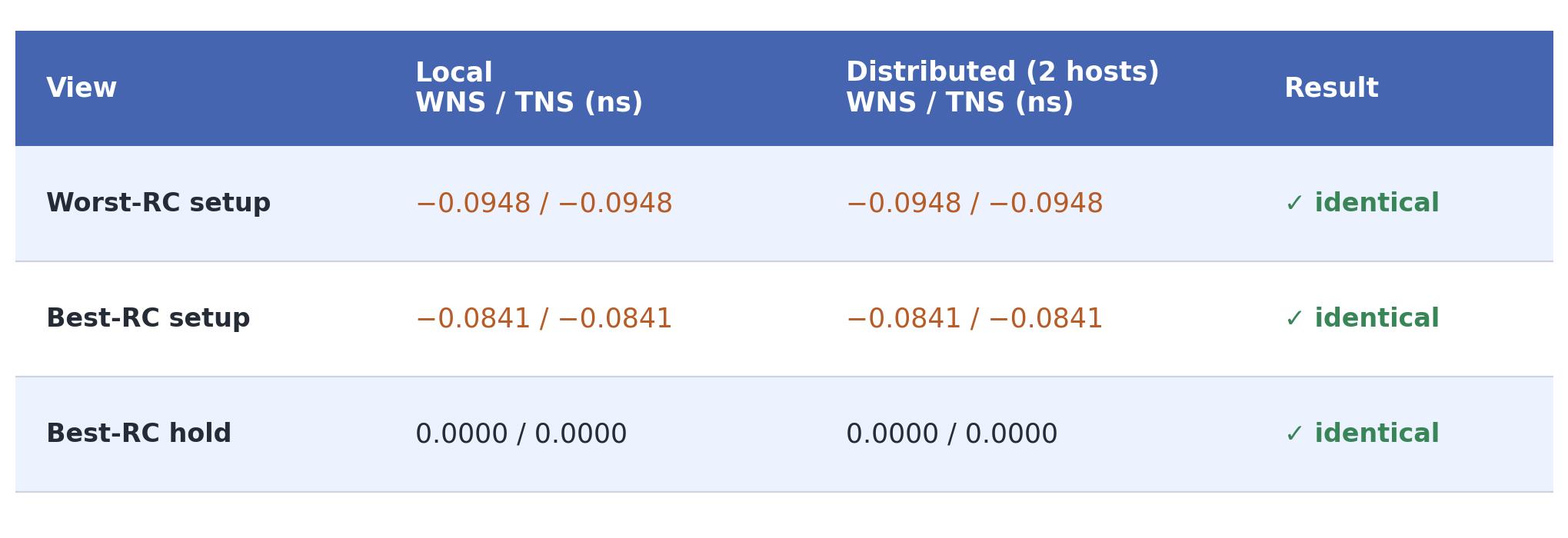
A common mistake is accepting a distributed run on a design where every view has zero slack. If a corner’s RC scaling were lost in transit, all-zero slacks would still match. Our acceptance test uses two RC corners scaled by 1.4× and 0.8× under a 0.14 ns clock, so that the setup views have distinct, non-zero violations. The two-host run reproduces the local run to the last displayed digit for every view: worst-RC setup WNS/TNS of −0.0948/−0.0948 ns, best-RC setup −0.0841/−0.0841 ns, and best-RC hold 0.0000/0.0000 ns. Endpoint and violation counts match as well. The two different setup numbers show that each view’s corner conditions reached the remote side.
A checklist you can use on any timing engine
- Build at least one testcase where you can re-derive every printed digit. If you can’t explain a digit, treat it as a bug.
- Use single-row tables and simple trees so that the interpolation and Elmore sums fit on one page.
- Take exception-priority tests from the documented examples, which already come with answers.
- Keep a SPEF golden case that includes unit multipliers, a corner triplet and a scaling factor.
- Test distributed timing for exact equality on a case where the corners give different non-zero slacks.
Golden testcases don’t replace large-design correlation. They make it meaningful: once the arithmetic is proven, any remaining disagreement must come from modelling choices, and those are worth discussing.
Dr. Sameer Pawanekar is Founder & CEO of Ramtera Inc. He holds a PhD from IIT Guwahati in placement and partitioning and an MTech from IIT Bombay, and was a postdoctoral researcher with the OpenROAD team at the University of California. Ramtera develops LVR, a physical verification engine, and PRE, a place-and-route engine.
Contact: [email protected] | https://ramtera.com | +91-7259103580
Also Read:
Share this post via:


The $725 Million Chip Development: Why Execution Risk, Not IP Cost, Now Dictates Advanced-Node Survival