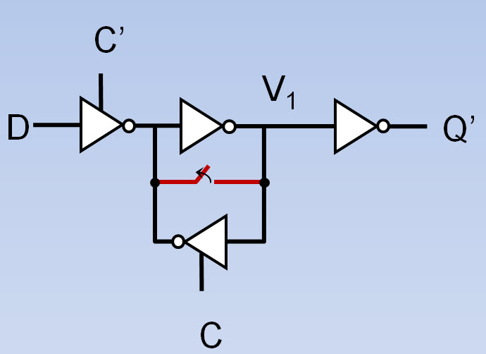
Estimating the MTBF of an SoC should always include an analysis of synchronizer reliability. Contemporary process nodes are introducing new challenges to the reliability of clock domain crossings so it is prudent to revisit how your simulation tool calculates a synchronizer’s MTBF. Let’s list the ten most common pitfalls.
- Shorting-nodes Method. Many in-house tools for estimating synchronizer MTBF use simulation to observe the time to settle to a valid voltage for two of the synchronizer’s nodes after they have been released from being shorted together. This method is problematic because in metastability the two nodes are unlikely to be at the same voltage. As a result the value of the time-constant obtained from the shorted-nodes experiment gives a poor estimate of Tau, the time-constant needed to estimate MTBF.

- Master-slave Time Constants Differ.Methods for measuring MTBF in silicon typically yield the Tau associated with the master. Measuring the Tau associated with the slave is problematic because of the extreme rarity of slave failure events. Often the slave Tau is much larger than that of the master and the resulting MTBF of the master-slave combination may be dangerously overestimated.
- Effect of Duty Cycle.When the Tau of the master and slave differ, clock duty-cycle can affect MTBF significantly. Thus, duty-cycle jitter or PLL bias must be included in the estimation of MTBF. Most contemporary synchronizer tools overlook this issue completely.
- Effect of Supply Voltage.Estimates of Tau depend critically on the supply voltage V[SUB]DD[/SUB]chosen for the simulation. Generally, the metastable voltage is about half the supply voltage and the closer this voltage is to the transistor threshold V[SUB]th[/SUB], the slower is the recovery to a valid logic voltage. This strong dependency of MTBF on V[SUB]DD[/SUB]requires the careful simulation of Tau and the analysis of MTBF for the worst-case, typically when ½V[SUB]DD[/SUB]approaches V[SUB]th[/SUB].
- Effect of Junction Temperature. Estimates of Tau depend critically on temperature, but because of the negative temperature coefficient of V[SUB]th[/SUB], cold temperatures are the ones that cause a significant reduction in MTBF.
- Verification of Simulation in Silicon. Of course, simulation tools should be compared with measurements in silicon by using transistor models derived from the parameters of the silicon under test. Also, these comparisons should be made over a range of temperature and voltage conditions. Otherwise the simulation tool is inadequate for the estimation of MTBF.
- Simultaneous Estimation of Tauand T[SUB]W[/SUB].Estimates of the metastability window T[SUB]W[/SUB]shift significantly with very small errors in Tau. A co-estimation technique that utilizes all the data obtained from simulations will yield the best joint estimation. This reduces the undesirable variability in T[SUB]W[/SUB] that can otherwise affect MTBF estimates.
- Effect of Loading.The circuit that loads the output of a synchronizer affects the settling time of the preceding synchronizer stage through capacitive coupling (think Miller). The resulting change in MTBF is significant and must be treated with extra care in multistage synchronizers.
- Multistage Synchronizer Formula Errors. Many published formulas for the calculation of multistage MTBF from individual stage parameters, produce results that disagree with simulations carried out on the complete synchronizer. In fact, these results are usually overly conservative, but in a few cases give an MTBF that is overly optimistic.
- Distribution of Clock-Data Offsets.If the sending and receiving clocks in a clock-domain-crossing are derived from the same oscillator through different PLLs, it is invalid to assume a uniform distribution of clock-data offsets to calculate the synchronizer’s MTBF. Depending on the value of the rational ratio of the clock rates, the MTBF can be either less than or greater than that given by the usual assumption of uniformity. Furthermore, it is hard to determine which is true, less than or greater than.
Many in–house tools for estimating the MTBF of synchronizers were developed before these pitfalls were completely understood. Fortunately, considerable progress has been made and better tools are now available. For example, MetaACEis available commercially and manages all of the ten difficulties listed above in one convenient simulation tool. You can learn more in these four papers: Node-shorting, MTBF bounds, Silicon measurements and Coherent clocks. Thanks to our colleague, Shlomi Beer, who did much of this work and then took the lead in preparing the papers.
lang: en_US


Flynn Was Right: How a 2003 Warning Foretold Today’s Architectural Pivot