IC designers involved with physical design are familiar with acronyms like DRC (Design Rule Check), LVS (Layout Versus Schematic) and DFM (Design For Manufacturing), but how would you go about checking for compliance with ESD (Electro Static Discharge) rules? You may be able to kludge something together with your DRC tool and some Tcl or Skill code, but it turns out that there is an easier approach by using a Programmable Electrical Rule Checker. At Mentor Graphics they’ve dubbed this product as Calibre PERC. I’ve blogged about PERC before, but I wanted to see what was new and decided to watch an on-demand web seminar where the emphasis was on actually using the tool.
This demo was conducted by Dina Medhat, TME at Mentor Graphics.

Dina explained that PERC can be used for three types of checks:
[LIST=1]
When I designed full-custom ICs at Intel we had a written circuit design methodology which embodied our best transistor-level practices, however we had no automated method to enforce these practices, it was a manual process with a senior circuit designer staring at schematics and IC layout looking for something out of place. Talk about tedious and error prone.
Seven ERC Checks
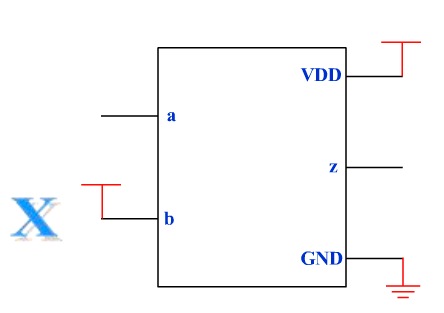
The first ERC check demonstrated was an input cell pin incorrectly tied to a power pin.
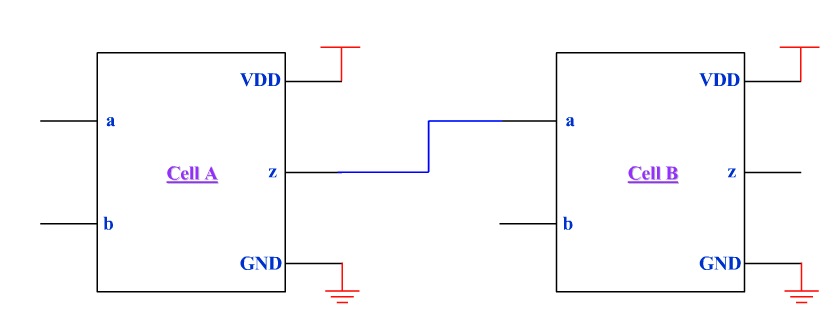
The second ERC check was finding two connected cells with different power supplies without a level-shifter cell.
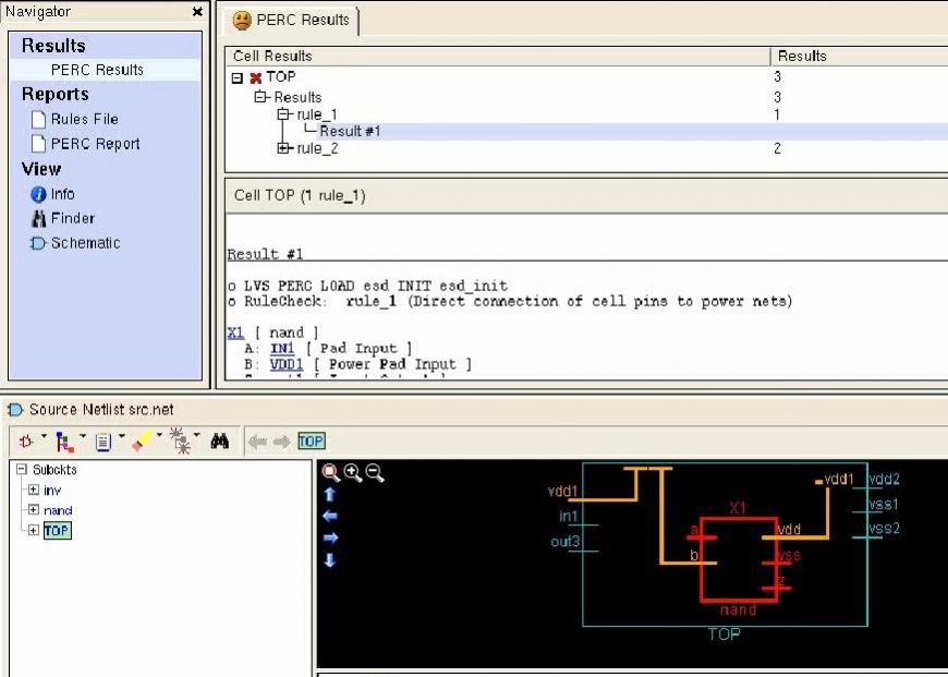
Rules were written for each of these cases and then a test design with each violation included was run through Calibre PERC. The output results looked very intuitive and descriptive to me because they pinpointed which rule was violated and where to find it in the schematic or layout views:
The violation for different VSS nets showed one cell using VSS1 (green) and the second cell using VSS2 (pink).
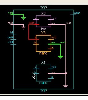
The GUI reminded me of using a web browser, because links opened up a schematic viewer that showed which rule was violated.
For ESD the first check had three constraints:
- Resistor must exist
- Resistor value must be greater than 100 ohms
- A Turn-off MOS device must exist
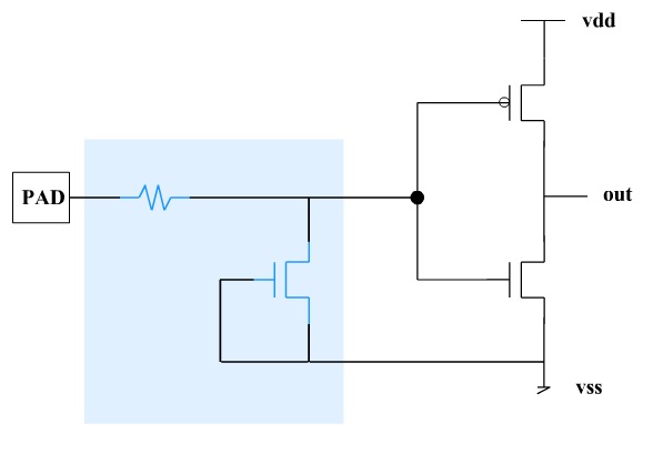
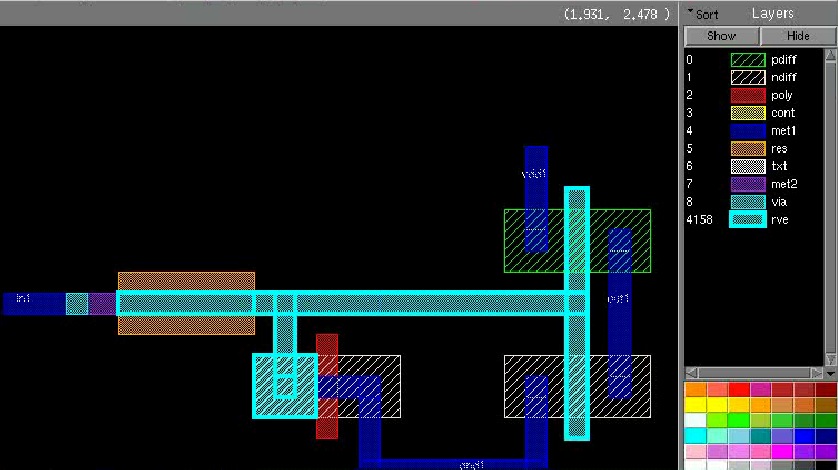
Each ESD constraint has a rule written for PERC, then it was run on a test layout showing results in both schematic and layout. The second constraint was violated in this layout because it had a Resistor value of only 65.0 ohms, instead of the spec of 100 ohms or more (shown in Orange):
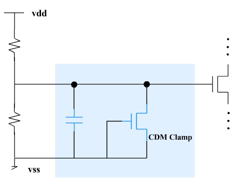
A second ESD check was looking for a CDM (Charge Device Model) clamp and capacitor configuration in a voltage divider network:
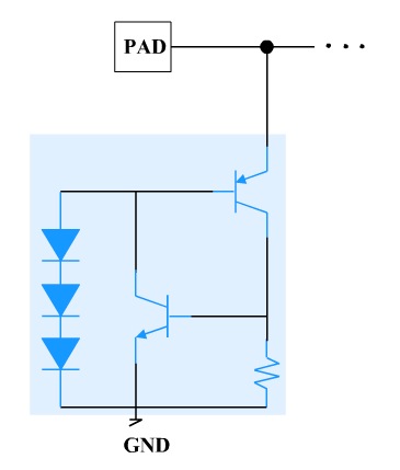
For the third ESD check they wanted to ensure that IO pads were all using protection devices with bipolar transistors, resistors and diodes in a specific topology:
Two checks were desired to validate design guidelines:
- Logic gates with common outputs cannot have different inputs
- Incomplete pass gates must be flagged
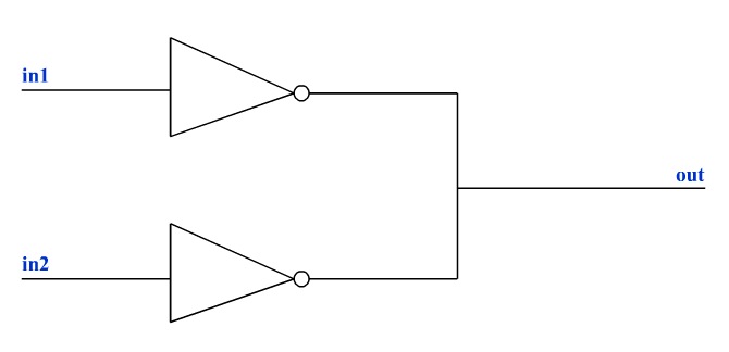
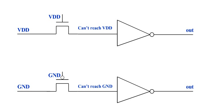
This demo didn’t show the details of how you write the rules, but I recall from previous discussions at Mentor that most rules take a dozen or so lines of code.
Summary
If you do transistor-level IC design and want to enforce your best practices, then consider using an automated approach with a tool like PERC.
Further Reading
- New ERC Tools Needed to Catch Design Errors that Lead to Circuit Degradation Failures, Feb 2011
- Transistor-Level Electrical Rule Checking, April 2011
- Improving Analog/Mixed Signal Circuit Reliability at Advanced Nodes, Dec 2011
- IC Reliability and Prevention During Design with EDA Tools, April 2012
- Automating Complex Circuit Checking Tasks, Sep 2012
- First Time, Every Time, Jan 2013
- ESD – Key issue for IC reliability, how to prevent?, Apr 2013
lang: en_US
Share this post via:


Semidynamics Unveils 3nm AI Inference Silicon and Full-Stack Systems