![SILVACO 051525 Webinar 400x400 v2[62]](https://semiwiki.com/wp-content/uploads/2025/04/SILVACO_051525_Webinar_400x400_v262.jpg)

I started out my engineering career by doing transistor-level circuit design and we used a proprietary SPICE circuit simulator. One thing that I quickly realized was that the accuracy of my circuit simulations depended entirely on the model files and parasitics. Here we are 40 years later and the accuracy of SPICE circuit simulations still depend on the model files and parasitics, but with the added task of using 3D field solvers to get accurate parasitic values, and even the use of 3D TCAD tools to model the complex physics of nm IC designs using FinFET transistors.
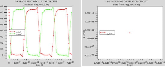
Foundries and IDMs both need a proven and accurate flow from TCAD to SPICE simulation for accurate FinFET behavior that match silicon measurements. This blog will consider such a flow using tools from Silvaco like DeckBuildor the Virtual Wafer Fab (VWF). I will start with an example circuit of a 9-stage ring oscillator using a FinFET technology with 20nm gate lengths:
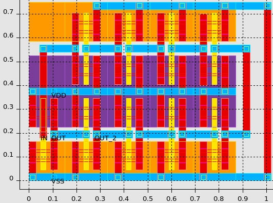
The next step is to create an annotated layout that identifies active devices (FinFET transistors) and the interconnect between the devices:
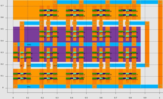
The initial IC layout is performed on a 2D representation, so the TCAD tool takes this 2D info as a starting point in doing a 3D process simulation where we get to choose process parameters like:
- Fin height
- Equivalent gate oxide thickness
- Source-drain diffusion times
With just a handful of input parameters the process simulator then automates the device meshing and creates a 3D representation of a p-channel FinFET including the SiGe source-drain stressors for mobility enhancement:
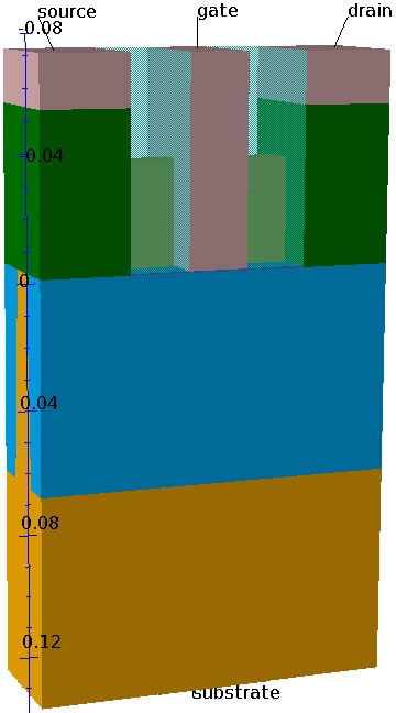
The 3D TCAD simulator Victory will automatically create the SPICE model files based on the p-channel and n-channel physical and electrical characteristics. Process engineers can iterate and investigate how different process parameters, strain and layout effects impact circuit performance (aka Design Technology Co-optimization).
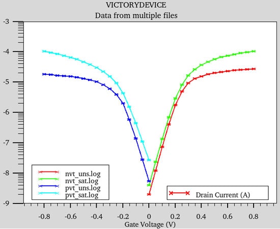
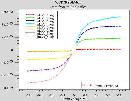
With a transistor model, you can then visualize the I-V curves for p and n transistors:
When running device simulations the process engineer decides which device physics to include:
- Standard model set
- Strain effects
- Gate tunneling
- Band to band tunneling
- User-defined effects
Finally, the BSIM-CMG models are created based upon these TCAD I-V curves and the 3D physics involved. In the 1970’s we only had proprietary models and SPICE simulators, but today we have model standards like BSIM-CMG which is approved by the Compact Modeling Council.
You can customized how your model cards are created if needed by using the UTMOST-IV GUI, but for this example a standard script was used without any tweaking. One quality control step is to check the difference between the original I-V curves and the generated SPICE model, look at how close these sets of curves are:
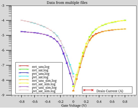
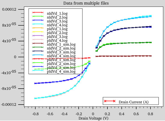
When I look at the TCAD curves versus SPICE model curves, the values are consistent. The Utmost-IV tool does have a full SPICE simulator that is used to fit the curves so closely, saving time for us and keeping the desired accuracy. So the transistors are well modeled in this tool flow and it’s time to look at the interconnect between devices.
Just as the FinFET devices required 3D modeling, the interconnect between FinFET transistors also requires a 3D field solver, Clever, to extract accurate resistance and capacitance values. The 3D Back End Of Line (BEOL) structure for the nine-stage inverter layout is shown below where Metal 2 is in Red, Metal 1 is Purple:
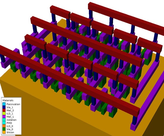
This 3D field solver produces the SPICE netlist which has both FinFET transistors and RC interconnect values.
An engineer can even run a large Design Of Experiments (DOE) with the Virtual Wafer Fab tool and use the built-in statistical features to fit response surface models, relating input variables to predicted outputs.
Running the SPICE netlist in the SmartSpice circuit simulator shows that the 9 stage ring oscillator is functioning properly (left plot), and we know the average power consumption (right plot).
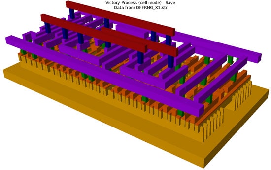
This same TCAD to SPICE model file flow was also run on a D-type Flip Flop from the Nangate digital library, here’s the 3D interconnect view:
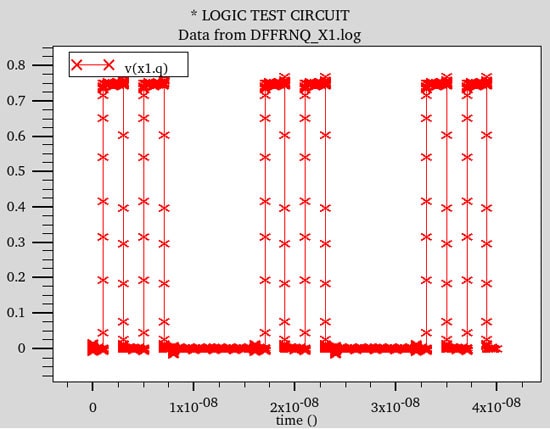
All possible logic states are simulated with SmartSpice on the Flip Flop netlist using extracted parasitics:
A CAD engineer could run many of these steps using the DeckBuild environment, or for further automation you should consider using the Virtual Wafer Fabtool instead. An example of using VWF is for a Design Of Experiments where a virtual split lot tree is built and run across many computers, where the final results are fitted to a Response Surface Model (RSM):
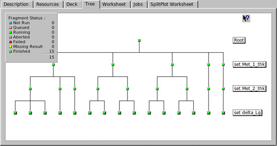
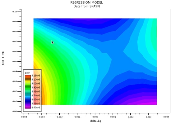
One insight from the RSM is that the maximum frequency is inversely proportional to the metal line width, to this particular circuit is parasitic capacitance limited, instead of resistance limited. Now the circuit designer knows how to better make trade-offs in reaching the requirements.
Summary
I’ve laid out the steps used by process engineers and CAD engineers to create SPICE model files:
- 3D TCAD simulation (Victory)
- SPICE model parameter extraction (Utmost IV)
- 3D netlist extraction (Clever)
- SPICE simulation (SmartSpice)
Silvaco has all four tools needed in this tool flow and they also added plenty of automation to save your team precious time (VWF) for performing Design Of Experiments. For more details read the recent article in Silvaco’s Simulation Standard online.
Related Blogs
- The Latest in Parasitic Netlist Reduction and Visualization
- SPICE Model Generation by Machine Learning
- Sometimes a Solver is a Suitable Solution


Comments
There are no comments yet.
You must register or log in to view/post comments.