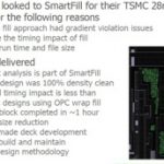
ads mdx semiwiki building trust gen 800x100ai

Fabless to OIP

Fabless to OIP
by Paul McLellan on 04-10-2013 at 7:22 pm

Suk Lee drew the short straw at the TSMC Symposium yesterday, with the 5pm slot. Not only late in the day but between all the attendees and free beer. The morning sessions had been standing room only, with several hundred standees (as they call them on muni around here, but isn’t a standee really someone being stood on?). But through the day numbers dwindled and the late afternoon sessions were not well-attended.


Suk started off with a little history of semiconductor. In the beginning there was a huge gap between what electronic companies wanted and the semiconductor and design expertise they had. Semiconductor expertise was entirely inside the few IDMs (although we didn’t call them that back then). Then ASIC companies came along, such as LSI Logic (where Suk worked) and VLSI Technology (where I did). We made it possible for people with no deep semiconductor knowledge to design their own chips. So the gap between what the people wanting the chips and the stuff the manufacturers knew started to close. TSMC was founded in 1987 ushering in the foundry era, and even physical design and circuit design moved out to system companies. The EDA industry came into existence. The gap closed.

But in the current era, it has opened up again. There is just too much to know. Plus design is more and more IP-based. Most companies, even if they wanted to design their own DDRx PHY (why would you?) don’t have the knowledge, for example. Another change is that the highest volume market is mobile. It ramps fast and then it’s on to the next node. So the mobile (and other markets, to be sure) designs need to tapeout before the process is completely stable. There is no point in building a multi-billion dollar fab in just a few months, hand out the design rules, and then have it sit idle while mobile companies design their chips.


So TSMC’s Open Innovation Platform (OIP) is a way to close that gap and acknowledge that tools, libraries, key IP and everything need to come together at the finish line just as the process is ready to ramp to volume. It is no longer possible even for a huge fabless semiconductor company to have all the knowledge they need, nor for the tool vendors to take their time since every process generation we can see looking forward, starting with 28nm, has a huge discontinuous feature. You can’t design 20nm without tools that understand double patterning. You can’t design 16nm without tools that understand FinFET. 10nm has more complex patterning rules, since it requires self-aligning double patterning and cut masks. I’ve no idea what 7nm needs and probably there are things nobody knows yet.


So OIP has to get a full reference flow together and delivered to early adopters much earlier than in the past. N20 (20nm) was faster than ever before but N16 (16nm) needs to be even faster.

OIP is a typical marketing name that doesn’t directly mean very much, but the reality is that getting designs to hit the fab when it is ready requires doing a lot of things much earlier than ever before. TSMC has been working with ARM for years, but more recently (again driven by mobile) they have started working with Imagination too.


Mentor U2U, Not Your Father’s User Conference

Mentor U2U, Not Your Father’s User Conference
by Paul McLellan on 04-10-2013 at 6:00 pm

I talked to Michael Buehler-Garcia about the changes Mentor is making to U2U, their user conference. It is in San Jose on April 25th at the DoubleTree.

Firstly, there are 3 great keynotes, two of whom I’ve seen speak before and can unreservedly recommend. Unfortunately I’m traveling that week and won’t be able to attend personally.

The first is Wally Rhines, who of course is Mentor’s CEO. But of the CEOs of the 3 big EDA companies I enjoy his keynotes the best, always rich with data and a few counterintuitive facts. He is talking about multi-disciplinary products, why they usually fail and some guidelines for success. This keynote opens the conference at 9am.

It is followed by Victor Peng, VP of the programmable platform group at Xilinx, speaking on The New Era of Heterogeneous Architectures and Integration Technologies. Although that title sounds pretty generic, he is actually talking about integrating different silicon technologies on 3D interposers using thru-silicon via (TSV) technology, an area where Xilinx has been a leader and has (I believe) the only interposer-based chip in volume production.

Then at lunchtime, Dr Chenming Hu, father of the FinFET and due to receive the Kaufman award at DAC, talks on FinFET is Only the Beginning. About a year ago I saw him talk at a GSA event and he gave the clearest explanation I’ve ever seen on why the two feasible technologies going forward are something like FinFET and something like FD-SOI (basically, the gate has to get thinner and so you either make it vertical and thin, or you put an insulator underneath it and make it thin that way). Don’t miss his talk. Not matter how much you know about FinFETs already, I bet you’ll learn something.

During the rest of the conference, Mentor has tried to make it more interactive and less being “lectured at”. It is a user-conference not a technology symposium. There are 10 minute gaps between all the presentations and usability pods manned by Mentor engineers in the hallways where people can ask questions and quickly get up to speed on something. Documentation of EDA tools is voluminous and although the answer may be in there, finding it is not always easy.

Another interesting session is at the end of the day. Dave Reed is talking about the Laker integration with Calibre RealTime. When this integration was first announced, Dave was at SpringSoft which had very little product overlap with Mentor. But SpringSoft was acquired by Synopsys and Dave runs marketing of the layout products. Of course Synopsys has lots of products that compete with Mentor but they are keeping the openness and integration. So despite, in one sense, Dave being the last guy you’d expect to show up at U2U, he’ll be there. By the way, Synopsys is also keeping all the open interfaces in SpringSoft’s Verdi product as I blogged about here.

The detailed agenda for the whole day is here. Details about attending, including a link to register are here. The conference is free and includes a free lunch (so there is such a thing).


Cadence Sues Berkeley Design Automation

Cadence Sues Berkeley Design Automation
by Paul McLellan on 04-10-2013 at 10:03 am

Cadence has brought a suit against Berkeley Design Automation for, as far as I can see, integrating their AFS circuit simulator with the Virtuoso Analog Design Environment (ADE) without using the (licensed) Oasis product. Since BDA is (actually was) a member of the Cadence Connections program, they have to abide by the contract which only allows them to create interfaces that their Connections legal contract allows. In particular “Member is not licensed to develop any interface to or translator for a Cadence product other than those specifically identified in exhibit x”.

Cadence does allow 3rd party simulators to be used with ADE but only if (a) the end-user has a license to Oasis, Cadence’s integration product and (b) the integration is done through Oasis. According to the complaint, BDA have circumvented commands within Virtuoso that require the Oasis license and their integration is not through Oasis, as a result of which end-users could use AFS with ADE without obtaining an Oasis license.

Cadence alleges that this is not just a breach of contract but is also a violation of the digital millennium copyright act (DMCA) and are seeking damages from BDA for loss of Oasis license fees, lost profits and so on. And, obviously, an injunction to prevent BDA from integrating AFS in this way.

Per the complaint, this came to light in mid-2012 when a Cadence engineer was trying to help a common customer troubleshoot ADE/AFS issues, and the customer showed them the BDA AFS installation guide which stated that “the Oasis integration is deprecated. BDA strongly discourages users from choosing this method.” The installation guide dates from 2010.

Of course I have no idea of the details of what or how BDA have implemented their integration, or whether most customers using the two products together did or did not have an Oasis license anyway although Cadence believes they did not.

According to a Cadence spokesperson, “Over many months before filing this lawsuit, Cadence made repeated proposals to work with BDA’s management to rectify this situation. Cadence was, however, unable to persuade BDA to comply with its contractual obligations under the Cadence Connections Program. Consequently, Cadence did not renew BDA’s participation in the Connections Program. Cadence is also seeking injunctive relief and damages for lost OASIS license fees, among other relief.”

Complaint PDF

Cadence Official Statement PDF

Berkeley Design and the Cadence Legal Action!


GlobalFoundries in Singapore

GlobalFoundries in Singapore
by Paul McLellan on 04-09-2013 at 11:12 pm

I hosted a webinar today for GlobalFoundries. Yes, I know that today was TSMC’s Technology Symposium, we weren’t that smart when we picked the date. It was basically a “fireside chat” with me as the moderator asking the questions and Paul Colestock and Aabid Husain as my guests. We actually did it at Cadence with ChipEstimate handling the logistics. And no, there wasn’t really a fireside.

The focus was on what Global actually manufactures in Singapore. It is a mixture of stuff but increasingly they are focusing on analog, which is defined as everything that isn’t digital. We all know that the leading edge FinFET stuff gets all the publicity, and in Global’s case their big fab 8 in Saratoga, NY. But, as Paul likes to point out, leading edge for a process depends on what you are doing with it. Sure, if you want to do a state-of-the-art digital SoC is is 28-16nm depending on whether you’re in production or starting a design. But if you want to do higher voltage stuff to address the automotive market that’s not going to work. It can’t handle the voltage, it’s years away from being qualified and so on. So a leading edge analog design may be in 130nm or 90nm or 45nm. That is where analog innovation occurs. Additionally, sometimes those designs run for years and years, since the cost of redesign exceeds the potential cost saving of moving down the process node ladder.

Another aspect of analog that is good from a foundry differentiation point of view is that the process really does matter. Of course it matters in 20nm but basically those transistors are switches and secret sauce is largely in the design, from the point of view of the fabless semiconductor company selling the chip. Not the same at all in analog. Innovation is still occurring in the devices themselves, because in analog they are not just switches.

Global has put in place modular process, built up from a basic process but with extra process steps depending on what is needed on the chip. Plus specialized options like BCD. This makes it possible to mix and match stuff, adding discretes and MEMS (mechanical stuff) if appropriate, handling different voltages. They have processes going up to hundreds of volts to handle the anticipated changes in both lighting (moving to LED) and motor control (going away from AC to DC with smart controllers, which is basically what hybrid cars have today).


They are putting half-a-billion dollars of investment into their Singapore fabs to expand 300mm capacity. Some analog runs in low volume or has tiny die and doesn’t benefit that much from bigger wafers, but large die and especially anything involving bumping can benefit a lot. The cost of bumping a 300mm wafer isn’t much more than the cost for 200mm, certainly not twice as much which is (roughly) the increase in the number of die. Lots of automotive and other analog markets use gold (and other) bumping a lot. The investment takes Singapore up to around a million wafer (8″ equivalent) starts per year.

I’ve been on lots of webinars before but this was my first time where we had no presentation, we just had a Q&A. Of course we planned what we were going to talk about but we couldn’t do much more or it would sound horribly scripted. In the end, everything worked out. We talked about all the things we planned. Analog is big, growing faster than semiconductor overall, but you have to make it scalable. Modular process, 200mm and 300mm wafers, GF is ramping up capacity in Singapore to 1M wpy.

The webinar was recorded and you can watch it here. I’ve not seen the replay yet…so your mileage may vary from my memories. Thanks to the over 50 of you who preferred to watch us to Morris Chang!


Manage your IC’s Stress for right performance

Manage your IC’s Stress for right performance
by Pawan Fangaria on 04-09-2013 at 9:30 pm

As we have moved towards lower process nodes to improve performance of ICs with higher density and functionality, many manufacturing effects have appeared which can render ICs useless, even though the layout design could be correct as per traditional design rules. What is more worrisome is the variability of these effects which depend on the proximity and surrounding of actual layout elements and hence is unpredictable before the layout is done. Actual layout needs to be considered to analyze these effects and action taken before final layout to keep the manufacturing abstraction level at the layout stage.

Variability due to Stress is a very prominent such effect which can significantly impact timing closure of the design. Timing characteristics from the standard cell characterization data no longer remain valid. Stress can also be induced intentionally in order to improve electron (for NMOS) and hole (for PMOS) mobility which can improve the drive current leading to higher performance. Unintentional stress is the manifestation of STI (Shallow Trench Isolation) and WPE (Well Proximity Effect). STI specifically depends on proximity of transistors in the layout and LOD (length of diffusion). Effects of these could be positive (if not negative) on the performance but that is unpredictable and cannot be relied upon. A typical example below shows how Isat current of NMOS and PMOS degrades with closer surrounding Poly –

Hence, Stress whether intentional or unintentional, needs to be modelled appropriately where current changes due to transistor structure and its surrounding geometry sizes such as well boundaries are captured and applied to produce a design layout which can result in correct working IC with intended performance.

Cadence, as being always innovative, provides a comprehensive solution for modelling and mitigating Stress induced variability at standard cell library development phase as well as post-route layout phase. A complete detail about the Stress, its impact and how Cadence tools handle those is given in its white paper at –
Modeling Stress-Induced Variability Optimizes IC Timing Performance White Paper

Cadence’s Litho Electrical Analyzer, Litho Physical Analyzer, Physical Verification and QRC Extraction tools provide an environment which can analyze standard cell library for variability over a number of different layout contexts and provide metrics (such as litho hotspots, gate variation, delay variation and leakage variation) for library designers to take corrective actions and for P&R tools (Cadence’s EDI system) to mitigate placement induced variability.

The extraction results are very robust as they take into account mobility, saturation velocity and threshold voltage parameters. The designer can optimize library in best possible manner as per architectural and layout tradeoffs.

Post-layout variability analysis can be done by both library designers and chip designers. Chip designers can use Litho Electrical Analyzer along with Encounter Timing System to identify, analyze and optimize the critical paths which may be sensitive to proximity effects.

[1 – flow for library designers, 2 – flow for chip designers]

Traditionally at higher process nodes sensitive circuitry is protected by using guard bands, but that is no more useful as Stress induced timing variations have become more pronounced at lower nodes. Tools for actual Litho analysis are needed to detect variation hot spots and manage them by adjusting the layout appropriately for the manufacturing success. Cadence provides an apt environment with specific tools for the same.


How Long Does it Take to Go From a Muddy Field to Full 28nm Capacity?

How Long Does it Take to Go From a Muddy Field to Full 28nm Capacity?
by Paul McLellan on 04-09-2013 at 4:02 pm


TSMC has a lot of capacity. Not just that, it has a lot more under construction. It currently has 3 300mm Gigafabs, fabs 12,14 and 15 (there doesn’t seem to be a 13). This morning, Dr Wang, who is TSMC’s VP of 300mm operations told us about the expansion plans. Currently fab 15 phase 3 and 4, and fab 12 phase 3 are to be ramped this year. Four more phases are under construction. Fab 14 phases 5, 6 and 7. And fab 12 phase 7. TSMC used to construct roughly one phase per year, now it builds 3. With all this capacity the will ramp to 13.5M wafers (8″ equivalents). Capacity in advanced nodes will double in advanced nodes (sub 45nm).

The ramp of 28nm into volume production was the fastest TSMC has ever done. 20nm/16nm will ramp even faster. Of course this is driven partially by the steep ramps and short product cycles of the mobile industry. Fabs 12/14 have thousands of engineers already preparing for that ramp.

Here is how 28nm ramped. In June 2010 fab 15 was a muddy field in Taichung. For 12 months the building and clean rooms were created. In another 10 months equipment move in and qualification took place. 22 months after breaking ground phases 1 and 2 of fab 15 started production output, TSMC’s first 28nm volume fab (of course there is a technology development research fab where the process was developed but that has very limited capacity).

You may have heard that TSMC had capacity problems at 28nm and this is true. But it is not true due to yield or capacity problems, it is entirely due to the major recession scaring off all the chip vendors and having them forecast a major drop in volume. But electronics is flying off shelves and so it turned out that by putting capacity in place for forecast demand there was not enough capacity for actual demand. More capacity is going in since phases 3 and 4 start next month which will take Fab 15 from 50,000 wafers per month to 100,000 wafers per month.

In Q1 2012 when the first two phases of fab 15 were nearing completion, production volume was zero wafers. By Q4 the fab was fully ramped to its 50,000 wafers/month capacity. So the answer to the question in the title is about 30 months from muddy field to full volume ramp complete.

It was even more of a challenge than it sounds in some ways. It was a new site (TSMC’s first fab there), a new team and a new technology.

Dr Wang went on to talk a bit about TSMC’s plans for 450mm wafers. Or rather the whole industry’s. The Global 450 Consortium was founded in March last year in Albany NY. TSMC is actually the general manager. The semiconductor equipment industry is moving forward with some prototypes now available.

From a technical point of view it looks like production tools should be available early in 2016 for everything except EUV. He has that in mass production in 2018. TSMC will build a pilot line in 2016-17 and ramp production after that, either on 10mm or 7mm depending on detailed timing of when equipment is really available in production volumes.

And yes, I know the last picture is actually fab 14. Even TSMC doesn’t seem to have a photo of fab 15 in its press photogallery.


RTL Power Optimization

RTL Power Optimization
by Paul McLellan on 04-09-2013 at 10:23 am

More so than most aspects of design, power reduction suffers from a paradox that early in the design cycle when the gains are the largest, the accuracy of power estimation is the lowest, and then late in the design cycle, when everything is known pretty much exactly it is too late to make anything other than trivial optimizations. The sweet spot seems to be at the RTL level. There is enough detail in the RTL that reasonable estimates of power can be calculated, but there is flexibility in the RTL (and the associated CPF/UPF power policy files) to be able to make significant savings. Before RTL is available, only rudimentary estimates of power by block are available. After RTL at the gate-level, the estimates are more accurate but the time to make significant changes has passed.

In the architectural stage, virtual platforms can be used to examine the effects of algorithmic techniques and the interaction of software with power reduction features such as powering off unused blocks. Between that, and the implementation flow itself when it is too late to do much more than select appropriate cells from the library and do basic clock gating, Atrenta has a portfolio of tools that can be used to reduce power at the RTL level.

These can be used to do the three different aspects of power optimization: analysis, modification and verification.


SpyGlass Power Verify allows analysis of voltage and power domains. These are, of course, specified in UPF or CPF depending on which toolsets are used for implementation.

SpyGlass Power Estimate allows power estimation and exploration at the RTL level. This requires power vectors since typically the vectors used for functional verification explore lots of corner cases that are not representative of normal behavior.

SpyGlass Power Reduce/Fix performs explicit and automatic sequential clock gating.

SpyGlass Power Memory Reduce removes redundant reads and writes from memory. When the address has not changed to the memory the previous latched value can be used, for example.

Using these tools on representative designs creates power reductions of 15-25% which is significant.

On Thursday this week Atrenta is having a webinar to cover RTL Power Optimization in detail, entitled “The 3 Dimensions of RTL Power Optimization.” It is on April 11th from 8.30am to 9.30am Pacific time. To pre-register go here.


SoC Power Integrity Challenges

SoC Power Integrity Challenges
by Daniel Payne on 04-08-2013 at 4:46 pm

At DAC in 2012 I visited a few dozen EDA companies and blogged 32 articles, however I didn’t get to see what Apache Design (now a subsidiary of ANSYS) had to say. I did have 20 minutes today to watch their latest video on SoC Power Integrity Challenges and decided to share what I learned. If you want to watch the video at Tech Online, then they will require you to register or login.
Continue reading “SoC Power Integrity Challenges”


Work With SemiWiki and Get Acquired?

Work With SemiWiki and Get Acquired?
by Daniel Nenni on 04-08-2013 at 4:27 pm

One of the nice things about being part of a website such as SemiWiki is that you get to see real-time trends and analytics. SemiWiki is built on top of a relational database with a full content manager and integrated analytics. It also allows us to see historical data that we can compare and contrast to what is happening today.

One of the more interesting trends that we see is acquisitions involving the companies we work with. For example, the following SemiWiki subscribers have been acquired over the last two years:

[LIST=1]

  • Apache (Ansys)
  • Magma (Synopsys)
  • Ciranova (Synopsys)
  • SpringSoft (Synopsys)
  • Tensilica (Cadence)

    If you take a deeper look into this trend you will see the common thread of Dr. Paul McLellan. Paul worked closely with all five of these companies and provided expert coverage based on his many years of experience in the semiconductor industry.

    Dr. Paul McLellan
    has a 30 year background in semiconductor and EDA with both deep technical knowledge and extensive business experience. He works as a consultant in EDA, embedded systems and semiconductor. Paul was educated in Britain and spent the early part of his career as a software engineer at VLSI Technology both in California and France, eventually becoming CEO of Compass Design Automation. Since then he was VP engineering at Ambit, corporate VP at Cadence, VPs of marketing at VaST Systems Technology and Virtutech, and interim CEO at Envis Corporation. He blogs at dac.com and at semiwiki.com and has published a book EDAgrafitti on the EDA and semiconductor industries.

    Looking forward, here are the other companies that Paul works closely with on SemiWiki:

    [LIST=1]

  • Atrenta
  • Calypto
  • Carbon
  • Jasper
  • Oasys
  • Pulsic
  • Runtime Design Automation

    Based on the analytics of this blog we can then rank the above companies based on who will be acquired next and by whom, pretty cool huh? That’s the difference between a Web 2.0 site like SemiWiki and a dusty old HTML gossip website. Seriously, when was the last time you went to the library and used a card catalog to find something?

    Take a look at the SemiWikiMergers and Acquisitions Wiki and see the colorful history of EDA acquisitions. Look at the bottom of the page and you will see that almost 20,000 people have viewed it thus far. Just to make things interesting, place your best guess in the comment section on who will be acquired next and by whom. Winners will get some SemiWiki swag.


  • Cutting the Key to 14nm Lithography

    Cutting the Key to 14nm Lithography
    by Beth Martin on 04-08-2013 at 2:30 pm

    It appears that immersion lithography is now the plan of record for manufacturing ICs at 14nm. How is it possible to use 193nm wavelength light at 14nm? How can we provide the process window to pattern the such tight pitches? The secret lies in computational lithography. For 20nm, the two key innovations in computational lithography involve enabling double patterning with concurrent OPC, and in improving difficult-to-print layouts with localized in-situ optimization and by using an inverse lithography technique.For 14nm, says Mentor Graphics’ OPC product marketing manager Gandharv Bhatara, computational lithography offers more tools for process window enhancement with better approaches to sub-resolution assist features (SRAFs). SRAFs have been used since the 130nm node for resolution enhancement, but for 14nm, SRAF placement has evolved considerably. In a recent article, Bhatara says that SRAF placement has moved from rules-based to model-based, and describes two new model-based approaches developed in the Mentor OPC tools. One approach uses inverse lithography (ILT) to create the golden reference for a rules-based SRAF placement. This gives superior process window for critical blocks like SRAM, where the rules are relatively easy to develop. The second approach is a true model-based approach, where a model is used to determine which areas on mask would benefit most from SRAFS and also to perform the initial SRAF placement. The model-based approach is particularly useful for random logic designs, where developing rules continues to be challenging. Both methods are good, but for different design styles. Bhatara says that for 14nm, combining them into a hybrid approach provides a single, unified SRAF recipe for SRAM (rules-based) and random logic designs (model-based). So if you need the keys to 14nm computational lithography, look for advanced SRAF solutions that provide flexibility, control runtime, and leverage both rules-based and model-based approaches.You can find this and other content on foundry-based IC design and manufacturing at www.mentor.com/solutions/foundry.