
The SEMI Industry Strategy Symposium (ISS) is Jan 13th-15th at the Ritz-Carlton in Half Moon Bay. When I discussed this with my beautiful wife as a possible business trip for us and mentioned the agenda she stopped me and said, “You had me at Ritz-Carlton!” As you can see by the picture it has a beautiful ocean view and includes a world class spa.
Will the combination of the unprecedented threat to Moore’s Law coupled with pressures of consumer products pricing and short life cycles stifle the industry or will the rapidly expanding mobile markets and pervasive computing trump the challenges and provide a new growth engine for the industry? How will chipmakers, equipment companies and materials suppliers be impacted and what strategies should they be contemplating now to deal with the new realities?
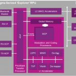
The mobile SoC market sure has changed the fabless semiconductor ecosystem. With wearable computing coming at us full force more change is coming, absolutely.
From business and economic trends to new and emerging markets, you’ll hear it all at the conference that has been delivering to the semiconductor industry for more than three decades—the SEMI Industry Strategy Symposium (ISS).
Paul McLellan will also be there so this will be a fully covered SemiWiki event. Engaging with semiconductor experts from around the world is not just our job, it is our privilege.
ISS 2014 hosts a hard-hitting lineup of executives and analysts offering valuable insights for companies up and down the supply chain. You’ll benefit from an array of information channels from company presentations and executive panels to the networking opportunities before, during and after the conference. The Industry Strategy Symposium, the only forum where senior executive suppliers and device manufacturers receive a first-hand view of what the industry will look like in the year ahead, and gain strategic insights into the shifting business environment. Take a look at the rich agenda and make plans now to attend.
Opening Keynote:
The Road Not Taken
Rick Wallace
President and CEO
KLA-Tencor
ISS Banquet Keynote:
Young Sohn
President and Chief Strategist
Samsung Electronics
Closing Keynote:
Manish Bhatia
Senior Vice President, WW Operations
SanDisk
Sessions
Day 1: Opportunities
- Opening Keynote
- Session 1: Economic Trends
- Session 2: Market Perspective
Day 2: Challenges
- Session 3: Technology Challenges
- Session 4: Opportunities at the Edge
Day 3: Outcome and Strategies
- Closing Keynote
- CEO Panel
SEMI is the global industry association serving the nano- and micro-electronic manufacturing supply chains. Our 1,900 member companies are the engine of the future, enabling smarter, faster and more economical products that improve our lives. Since 1970, SEMI has been committed to helping members grow more profitably, create new markets and meet common industry challenges. SEMI maintains offices in Bangalore, Beijing, Berlin, Brussels, Grenoble, Hsinchu, Moscow, San Jose, Seoul, Shanghai, Singapore, Tokyo, and Washington, D.C. For more information, visit www.semi.org.
lang: en_US


