BannerforSemiWiki 800x100 (2)

ESD at TSMC: IP Providers Will Need to Use Mentor to Check

ESD at TSMC: IP Providers Will Need to Use Mentor to Check
by Paul McLellan on 01-22-2014 at 1:24 pm

I met with Tom Quan of TSMC and Michael Beuler-Garcia of Mentor last week. Weirdly, Mentor’s newish buildings are the old Avant! buildings where I worked for a few weeks after selling Compass Design Automation to them. Odd sort of déja vu. Historically, TSMC has operated with EDA companies in a fairly structured way: TSMC decided what capabilities were needed for their next process node, specified them and then the EDA companies developed the technology. It wasn’t quite putting out an RFP, in general TSMC wasn’t paying for the development, the EDA companies would recover their costs and more from the mutual customers using the next node.

The problem with this approach is it doesn’t really allow for innovation the originates within the EDA companies. Mentor and TSMC have spend the last couple of years working very cooperatively on a flow for checking ESD (electro-static discharge), latchup and EOS (electrical overstress). All of these can permanently damage the chip. ESD can be a major problem during manufacture, manufacturing test, assembly and even in the field. EOS causes oxide breakdown (some one-time programmable memories use this deliberately to program the bit cells, but when it kills other kinds of transistors it is a big problem). Like most things, it is getting worse from node to node, especially 20nm and 16nm. The gate oxide is getting thinner and so it is simply easier to damage. FinFETs are even more fragile.


Historically TSMC has had layout design rules for these types of issues. But they required marker layers to be added to the cells to indicate which checks should be done in which areas. This causes two problems. Adding the marker layers is tedious and not really very productive work. But worse, if the marker layers are wrong then checks can be omitted and, often, without causing any DRC violations to give a hint that there is a problem. Another issue is that the design rules from 20nm on are sometimes voltage dependent, again a solution that was addressed historically with marker layers. Even then, not all rules could be checked. In fact, previously 35% of rules could not be checked and 65% required marker layers to check.

This is increasingly a problem. It is obviously not life-threatening if the application processor in your smartphone fails (although obviously more than annoying). But medical, automotive and aerospace have fast growing electronic content and they have much higher reliability requirements. If your ABS system or your heart pacemaker fails it is a lot more than annoying.

So Mentor and TSMC decided that they wanted a flow for checking that didn’t require marker layers and covered all the rules. It would obviously need to pull in not just layout data, but netlist and other electrical data (voltage dependent design rules obviously require knowing the voltages). The flow is intended for checking IP as part of the TSMC9000 IP quality program.

This is built on top of Mentor’s PERC (programmable electrical rule checker). They focused on 3 areas where these problems occur:

  • I/Os (ESD is mostly a problem in I/Os)
  • IP with multiple power domains
  • analog

Voltage dependent DRC checking is another area of cooperation. Many chips today have multiple voltages. In automotive and aerospace these may include high voltages and, as a general rule, widely separated voltages require widely separated layout on the chip to avoid problems. Again, the big gains in both efficiency and reliability come from avoiding marker layers.


The current status is that Calibre PERC is available for full-chip checking 28nm, 20nm with 16nm in development. As part of the IP 9000 program it is available for IP verification for 20SoC, 16FF and 28nm. Use of Calibre PERC will become a requirement (currently it is just a recommendation) in 20nm, 16nm and below.



More articles by Paul McLellan…


Have you Tried ALDEC?

Have you Tried ALDEC?
by Luke Miller on 01-22-2014 at 1:00 pm

I must admit. I was too comfortable. Let me explain, I’m a ModelSim guy from Mentor Graphics. I did not really think nor care much of the other RTL simulator options. How could someone build a better tool with respect to simulation? Let me introduce you to Aldec. Aldec was founded in 1984 by Dr. Stanley M. Hyduke. 30 years later they are still in business and growing strong. I think I heard of them once in my other life but had no time nor money to perform an evaluation of their software. Well, I get a second chance. Before I get into this I must note that my opinion has not changed, HDL coding will become less and less BUT on all FPGA design HDL coding will always be needed to mesh together all the sub-components. Aldec seems to compliment this very well including VHDL 2008 Support. So I still recommend using Xilinx’s Vivado HLS to design much of your DSP and other cores and then use Aldec to tie the wrapper and the design together. Note that these tools are all pre-synthesis tools.

Aldec today has over 30,000 active worldwide licenses. Now here is a bit of writing genius, but that is a lot of licenses. I know if you are like me, one of the major concerns when using any new tool is the health and size of a company. That is, what if I switch over to the Aldec tool suite and they go belly up? That is a realistic concern, remember the PA Semi days! I do! Let me be the first to assert that Aldec is a very healthy company, with a large user base, active software developments and world class help. That means you can pick up a phone and talk with a real person based in the United States. That is all important. They can also tailor some of the tools and license options as well. For example say your company needs 5 licenses but during design sign off, you need 50 licenses. That’s easy, they will pro rate your licenses for the time you need the extra licenses without any extra penalty. Aldec licenses are worldwide and not node locked to a particular geographic location. That equates to more cost savings.

Before I go into any deep dive, there are few tools I would like to review over the course of this year. I highly encourage you to go to the Aldec website and study what is available to accelerate your FPGA design cycle.

Active-HDL is a Windows® based, integrated FPGA Design Creation and Simulation solution for team-based environments. Active-HDL’s Integrated Design Environment (IDE) includes a full HDL and graphical design tool suite and RTL/gate-level mixed-language simulator for rapid deployment and verification of FPGA designs.

The design flow manager evokes 120+ EDA and FPGA tools, during design entry, simulation, synthesis and implementation flows and allows teams to remain within one common platform during the entire FPGA development process. Active-HDL supports industry leading FPGA devices including Xilinx and even Xilinx Zynq.

ALINT design analysis tool decreases verification time dramatically by identifying critical issues early in the design stage. Smart design rule checking (linting) points out coding style, functional, and structural problems that are extremely difficult to debug in simulators and prevents those issues from spreading into the downstream stages of design flow. The tool features highly tune-able and intuitive framework that seamlessly integrates into existing environments and helps to automate any existing design guidelines. The framework delivers configurable sets of rules, efficient Phase-Based Linting (PBL) methodology, and feature rich result-analysis tools that significantly improve user productivity and overall efficiency of the design analysis and refinement process.

Riviera-PRO™ addresses verification needs of engineers crafting tomorrow’s cutting-edge FPGA and SoC devices. Riviera-PRO enables the ultimate test bench productivity, re-usability, and automation by combining the high-performance simulation engine, advanced debugging capabilities at different levels of abstraction, and support for the latest Language and Verification Library Standards.

My next blog will walk my readers thru a real design using the ALDEC tools! Stay tuned!

lang: en_US


Just Released! Fabless: The Transformation of the Semiconductor Industry

Just Released! Fabless: The Transformation of the Semiconductor Industry
by Daniel Nenni on 01-22-2014 at 12:00 pm

The book “Fabless: The Transformation of the Semiconductor Industry” is now available in the Kindle (mobi) and iBooks (ePub) formats. We are really looking forward to your feedback before we go to print in March. This was truly a Tom Sawyer experience for me. As the story goes Tom made whitewashing a fence seem like fun so his friends would do the work for him.

Paul McLellan was my first friend. Paul and I met during the EDA’s Next Top Blogger Contest at DAC in 2009 and we lost! Paul has since proven them wrong as he is without a doubt EDA’s Top Blogger publishing 279 blogs on SemiWiki in 2013. What I discovered in writing this book is that as a blogger I can only write 500 words at a time so Paul had to fill in the rest. His depth of semiconductor knowledge and willingness to trust me is unparalleled.

My next friends were companies that work with SemiWiki. Since this is a book chronicling the rise of the fabless semiconductor ecosystem, having the companies that actually participated in that rise contribute sub chapters made complete sense. This was much more of a challenge than I imagined. Fortunately, Mentor is a very game company and they contributed first, then came TSMC, Xilinx, Cadence, Synopsys, ARM, Imagination Technologies, VLSI Technology, Chips and Technology, Global Unichip, GLOBALFOUNDRIES, and eSilicon.

Book Preview

The real challenge in writing a book like this is how to end it. “Chapter 8: What’s Next For The Semiconductor Industry?” was simply brilliant if I say so myself. Getting 300 word passages from CEO’s and other executives of the top companies in the fabless semiconductor ecosystem was not easy! But again, Mentor’s CEO Wally Rhines went first. After that it was an avalanche:

Cliff HouVice President Research and Development of TSMC (book Foreword)
Moshe Gavrielov President and CEO of Xilinx, Inc.
Simon Segars CEO of ARM

Aart de GeusChairman and Co-CEO of Synopsys, Inc.
Lip-Bu TanPresident and CEO of Cadence Design Systems
Walden RhinesCEO and Chairman of Mentor Graphics
Subi KengeriVice President Advanced Technology Architecture of GLOBALFOUNDRIES
Ajoy BoseChairman, President, and CEO of Atrenta Inc.
Jack HardingPresident and CEO of eSilicon
Kathryn KranenCEO of Jasper Design Automation
Hossein YassaieCEO of Imagination Technologies
Sanjiv KaulCEO of Calypto Design Systems
Srinath AnantharamanFounder and CEO of Cliosoft
Charlie JanacPresident and CEO of Arteris
David HallidayCEO of Silvaco
John TannerFounder and CEO of Tanner EDA
Xerxes WaniaPresident and CEO of Sidense
Ghislain KaiserCo-founder and CEO of Docea Power
Jodi SheltonCo-founder & president of the Global Semiconductor Alliance
Gideon WertheizerCEO of CEVA, Inc
Grant PierceCEO of Sonics, Inc
Trent McConaghyCo-founder and CTO of Solido Design
Mike JamiolkowskiCEO of Coventor, Inc.
Joe SawickiVice President and General Manager at Mentor Graphics
Martin LundSenior VP of the IP Group at Cadence Design Systems
Rich GoldmanVice President of Corporate Marketing and Strategic Alliances at Synopsys
Raymond LeungVP of SRAM at Synopsys
Richard GoeringVeteran EDA editor and author of the Cadence Industry Insights Blog

There are also passages from the SemiWiki bloggers, myself included, which I think you will find interesting. The book is a very good read, it’s for the greater good of the fabless semiconductor ecosystem, I sincerely hope you enjoy it!


A Power Optimization Flow at the RTL Design Stage

A Power Optimization Flow at the RTL Design Stage
by Daniel Payne on 01-21-2014 at 10:20 pm

SoC designers can code RTL, run logic synthesis, perform place and route, extract the interconnect, then simulate to measure power values. Though this approach is very accurate, it’s also very late in the implementation flow to start thinking about how to actually optimize a design for the lowest power while meeting all of the other design requirements. Ideally, you would want a flow that starts with your RTL code at the design phase and then provides a method to estimate power and even provide feedback on how to best reduce power long before physical implementation even begins.

Here is a flow-chart for such a methodology where power estimation happens early during the design phase, instead of too late:

The first box depicts how at the architectural stage a decision is made about using voltage domains, power domains, and clock gating techniques. Any IP re-used from a previous design can be quickly tallied in this new design for an early power estimate.

At the second box you should have enough RTL together so that power numbers can be added up based on re-use or spreadsheet estimates. There’s even commercial EDA software from Atrentacalled SpyGlass Power that can quickly estimate power numbers at the RTL design phase. Either the manual or automated approach will benefit your project early in the process to see if the power requirements have been met.

Most designs will not be within the power budget at this early design stage, so it’s time to move on to the third step: Power Reduction methods. The SpyGlass Power tool will help automate this power reduction process by changing an RTL design:

  • Applies gate enables, then provides an activity-based power calculation
  • Inserts clock-gates
  • Checks existing clock enable
  • Identifies new clock enables

You are likely also adding level shifters between voltage domains and inserting isolation logic. These changes and SpyGlass Power changes need to be verified against the original design intent, which is the fourth step in the flow-chart.

Implementation is the fifth step and it’s where logic synthesis transforms RTL into technology-specific cells for use by a place and route tool, driven by timing, DFT and placement constraints.

Once the IC layout is complete a final post-layout power verification is required to ensure that no surprises or errors have crept in.

Power Saving Overview

SoC power can be divided into dynamic and static categories. Examples of controlling dynamic power are:

  • Using voltage domains
  • Adding clock gating techniques

And examples for managing static power include:

  • Multiple power domains where an entire domain can be put to sleep
  • Using multi-voltage threshold transistors

Power Estimation in SpyGlass Power

This tool can calculate power by cycle, average for leakage, internal and switching, then display it graphically or numerically:

Power Reduction

Pawan Fangaria blogged recently about many of the clock gating techniques used for power reduction in more detail. Taking automation one step further SpyGlass Power has a feature called AutoFix that finds new clock enable opportunities then goes ahead and fixes the RTL code to take advantage of it.

To put your mind at ease about the integrity of any changes to RTL you can run a sequential equivalency checking (SEC) tool on the original RTL versus AutoFixed version.

Summary

Estimating and reducing power are popular topics for SoC designers today, fortunately we have EDA tools in place by vendors like Atrenta that help automate the task in a timely fashion by letting you work with early RTL to see if your power requirements are being met.

Further Reading

A 12 page white paper from Guillaume Boillet and Kiran Vittal is available at Atrenta, and you’ll need to complete a simple registration process before downloading.

lang: en_US


TSMC Responds to Intel’s 14nm Density Claim!

TSMC Responds to Intel’s 14nm Density Claim!
by Daniel Nenni on 01-21-2014 at 9:30 pm

TSMC responded to Intel’s 14nm density advantage claim in the most recent conference call. It is something I have been following closely and have written about extensively both publicly and privately. Please remember that the fabless semiconductor ecosystem is all about crowd sourcing and it is very hard to fool a crowd of semiconductor professionals, absolutely. To see Intel’s infamous density presentation click HERE.


First let’s take a look at what TSMC had to say:

Morris Chang – Chairman:So I now would ask Mark Liu to speak to TSMC’s competitiveness versus Intel and Samsung:

Let me comment on Intel’s recent graph shown in their investor meetings, showing on the screen. I — we usually do not comment on other companies’ technology, but this — because this has been talking about TSMC technology and, as Chairman said, has been misleading, to me, it’s erroneous based on outdated data. So I’d like to make the following rebuttal:

On this new graph, the vertical axis is the chip area on a large scale. Basically, this is compared to chip area reduction. On the horizontal axis, it shows the 4 different technologies: 32, 28; 22, 20; 14, 16-FinFET; and 10-nanometer. 32 is Intel technology, and 28 is TSMC technology so is the following 3 nodes, the smaller number, 20, around — 14-FinFET is Intel, 16-FinFET is TSMC. On the view graph shown at Intel investor meeting, it is with the gray plot, showing here. The gray plot showed the 32- and the 20-nanometer TSMC is ahead of the area scaling and — but — however, with 16, the data — gray data shows a little bit uptick. And following the same slope, go down to the 10-nanometer, was the correct data we show on the red line. That’s our current TSMC data. The 16, we have in volume production on 20-nanometer. As C.C. just mentioned, this is the highest density technology in production today.

We take the approach of significantly using the FinFET transistor to improve the transistor performance on top of the similar back-end technology of our 20-nanometer. Therefore, we leverage the volume experience in the volume production this year to be able to immediately go down to the 16 volume production next year, within 1 year, and this transistor performance and innovative layout methodology can improve the chip size by about 15%. This is because the driving of the transistor is much stronger so that you don’t need such a big area to deliver the same driving circuitry.

And for the 10-nanometer, we haven’t announced it, but we did communicate with many of our customers that, that will be the aggressive scaling of technology we’re doing. And so in the summary, our 10 FinFET technology will be qualified by the end of 2015. 10 FinFET transistor will be our third-generation FinFET transistor. This technology will come with industry’s leading performance and density. So I want to leave this slot by 16-FinFET scaling is much better than Intel’s set but still a little bit behind. However, the real competition is between our customers’ product and Intel’s product or Samsung’s product.

Morris Chang – Chairman:Thank you, Mark. In summary, I want to say the following: First, in 2014, we expect double-digit revenue growth and we expect to maintain or slightly improve our structural profitability. As a result, we expect our profit growth to be close to our revenue growth. In 2014, the market segment that most strongly fuels our growth is the smartphone and tablet, mobile segment. The technologies that fuel our growth are the 20-SoC and the 28 high-K metal gate, in both of which we have strong market share. In 2015, our strong technology growth will be 16-FinFET. We believe our Grand Alliance will outcompete both Intel and Samsung, outcompete.

If there is anyone out there that doubts these numbers please post in the comment section or send me a private email. I will follow up with a rebuttal blog based on feedback next week.

More Articles by Daniel Nenni…..


Semiconductor IP and Correct-by-construction Workspaces

Semiconductor IP and Correct-by-construction Workspaces
by Daniel Payne on 01-21-2014 at 8:00 pm

SoC hardware designers could learn a thing or two from the world of software development, especially when it comes to the topic of managing complexity. Does that mean that hardware designers should literally use a software development environment, and force fit hardware design into file and class-based software methodologies? I don’t really think so, but it would make sense for hardware designers to use some best practices from software development that have been adapted to the unique IP-centric world of SoC design where it’s becoming more common to use hundreds of IP blocks.

A workspace is the name give to environment where SoC design including IP content and the metadata used to describe it are managed, and changes to IP are tracked. You could manually create workspaces and then manually track IP changes with a general purpose tool like Excel, however it would likely consume weeks of valuable engineering effort and the results would be error prone because you would have to manually alert other designers on your team every time a change to IP was made.

Manually managed workspaces introduce more issues like: the security of certain IP and who should have access, selecting the correct IP versions to avoid errors, and keeping network traffic and disk usage at a minimum.

Correct-by-construction Workspaces

Now that we know the risks of using a manual process, let’s define what a correct-by-construction workspace methodology should do for us:

  • Centralized Management of all IP, where any change is automatically propagated to anyone of the design team.
  • Centralized security by assigning the proper access to each IP block by each team member.
  • Minimized disk usage by using a common, read-only version of IP blocks.
  • View management where a designer can see all data views required.
  • Multi-site support so that teams spread around the globe can see and use the IP to get their projects completed with a minimum latency, low network traffic and low disk storage.

Hardware design is not Software design

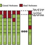
Chip designers run regressions, simulations and physical verifications that can take from minutes to days, and can consume large amounts of RAM and disk space, so it’s not practical to treat this like an Agile software development process that relies upon a “top-of-tree” approach. For SoC design a feasible approach is to to track which blocks have been fully verified in the context of the whole design, then add that to a certified top-of-tree:

ProjectIC from Methodics

Engineers at Methodicshave created ProjectIC as a platform to manage the IP lifecycle for both chip and IP designs that does create and track correct-by-construction workspaces.

One commonality between software and hardware development is that ultimately they are just collections of files. Popular data management tools like Perforce can be used for both hardware and software disciplines, however additions must be made to support an IP-centric design methodology. Hardware designs need to track IP metadata and have an IP abstraction layer enabled by IP metadata to be effective:

Features on top of data management for ProjectIC that enable correct-by-construction workspaces are:

  • An IP catalog to list which IP release can be used.
  • Central definitions so that you can control IP configurations for your design.
  • Security through permissions control.
  • Task specific workspaces for an IP block being designed.
  • View management so that an RTL designer doesn’t need to check out the physical layout view.
  • Automatic notifications of any new IP block release to anyone that is using that block.
  • Minimized disk space usage by having remote or local data available to a workspace.

Further Reading

There’s a four page white paper from Methodics that goes into more detail and it can be downloaded here. There you’ll read about:

  • Workspace management in practice
  • Creating a workspace
  • Editing Local IP data
  • Releasing an IP
  • Managing defects
  • Improved collaboration

Another related white paper is called Data Management Best Practices, which covers how to effectively use DM for hardware design. There’s a brief registration process before you can download either white paper.

Conclusion

A correct-by-construction workspace approach will save you time, effort and provide peace of mind over a manually managed workspace methodology.


DSPs converging on software defined everything

DSPs converging on software defined everything
by Don Dingee on 01-21-2014 at 5:00 pm

In our fascination where architecture meets the ideas of Fourier, Nyquist, Reed, Shannon, and others, we almost missed the shift – most digital signal processing isn’t happening on a big piece of silicon called a DSP anymore.

It didn’t start out that way. General purpose CPUs, which can do almost anything given enough code, time, power, and space, were exposed as less than optimal for DSP tasks with real-world embedded constraints. In order for algorithms to thrive in real-time applications, some kind of hardware acceleration was needed.

The DSP-as-a-chip emerged, with tailored pipelining and addressing modes wrapped around multiply-accumulate stages, and in more modern implementations larger word widths and parallelism. Popular general purpose DSP families from Analog Devices, Freescale, TI, and others still exist today, making up about 8% of market revenue according to Will Strauss.

What happened? As DSP became part of more systems, technology diverged targeting specific portions of a system with its capability, in the mix with other more general purpose resources. Four other methods enabling signal and image processing algorithms appeared:
[LIST=1]

  • Programmable logic and IP, in FPGAs from Altera and Xilinx et al,
  • In-line vector instructions, such as ARM NEON or Freescale AltiVec or Intel AVX,
  • Vector execution units, typical of modern GPUs from AMD and NVIDIA,
  • IP cores for SoCs, including those from CEVA, Coresonic, or Cadence Tensilica.

    For every divergence, there is a convergence. Today, flexibility for more than one application is the name of the game, and that is breaking the boundaries between device types. GPUs are morphing into more than just graphics engines, CPUs want to do some DSP algorithms, and DSPs and FPGAs both crave partner cores for more general purpose work.

    This is giving rise to new combinations of general purpose cores and DSP capability for acceleration of key functions. Looking at recent multicore developments – TI KeyStone, Xilinx Zynq, NVIDIA Tegra K1 to name a few – the trend is becoming obvious. By no means does this imply these parts are exactly interchangeable, just that the trend is headed away from the traditional DSP-as-a-chip toward a multicore blend of functions.

    So, it shouldn’t be a surprise these influences are also changing how DSP IP cores are evolving, getting beyond specialized point functions such as audio and baseband interface. By definition, a DSP IP core sits astride an ARM or other processor core, fitting into the trend we’ve identified. This brings opportunities in interconnect and cache coherency, along with new possibilities.
    In a marked departure from the traditional DSP architecture, CEVA has uncorked the XC4500, with features borrowed from almost all the approaches we’ve talked about converging in a single part. Paul McLellan introduced us to the XC4500 last fall, but I’ll mention two items briefly. First is a vector processing element, able to rip through over 400 16-bit operations in a single cycle. Second is the interface between the vector engine and several CEVA-defined plus open to user-defined co-processors, which CEVA terms “tightly coupled extensions”.

    It’s a huge jump from DSP point functions in mobile handsets into a crowded field of wireless infrastructure solutions. Will CEVA succeed here? We should keep in mind the Internet of Things is driving us into new territory: software defined everything. Just as the DSP-on-a-chip is no longer the entire processor, the radio is now no longer the entire product. Efficient operation in the space between subscribers and the cloud is going to require a lot more than just protocol engines and baseband processing, and the workload-tuned CEVA XC4500 is another good example of processor evolution.

    My guess is what we will see from CEVA and others is a learning cycle or two, where these new DSP architectures continue to evolve, and new application ideas emerge as the right combinations of features and ways for partner cores to use them are discovered. Designers will have to get used to multiple, formerly separate disciplines of thinking – DSP plus vector engine plus ARM core, all tied together via software, being a good example – and how to best partition and coordinate software to achieve system goals.

    At the spot software defines everything, the new DSP convergence will probably be found.

    More Articles by Don Dingee…..

    lang: en_US


  • Happy Birthday GSA

    Happy Birthday GSA
    by Paul McLellan on 01-21-2014 at 2:57 pm

    This year marks the 20th anniversary of GSA and collaboration around the foundry and fabless ecosystem. Originally GSA was FSA, the fabless semiconductor association. There was a semiconductor associations 20 years ago, the SIA, but that was still the “real men have fabs” era and fabless semiconductor companies were not considered “real” semiconductor companies and so were excluded. Now, of course, nobody would claim companies like Qualcomm, Broadcom, Xilinx are not real semiconductor companies. Going forward, only Intel and Samsung have their own fabs to build their own chips. And both of them also have at least some foundry business and so participate in the fabless ecosystem too.

    During the year each month there GSA will be producing video interviews with industry leaders discussing GSA. The first one is features Steve Mollenkopf of Qualcomm, Scott McGregor of Broadcom, Mark Edelstone from Morgan Stanley and more.

    GSA also has 2 technical working group meetings this week that are open for registration.
    What: 3DIC Packaging Working Group Meeting
    When: Wed, JAN 22, 2014 | 2:00 PM – 5:00 PM
    Where: Altera, 101 Innovation Drive, San Jose, CA 95134
    Why: The industry is developing 3D-IC related standards to help ensure interoperability and minimize development time. The Q1 3DIC Working Group meeting will focus on:

    • Altera’s 3D-IC Strategy with Arif Rahman, Architect
    • Standards update from Si2, SEMI, and IPC

    Register here

    What: IP Working Group Meeting
    When: Thurs, JAN 23, 2014 | 9:00 AM – 12:00 PM
    Where: Synopsys, 700 E. Middlefield Road, Bldg 8, Mountain View, CA, 94043
    Why: Widely used interfaces help drive IP development, and MIPI technology, used in mobile applications, is such an interface. The Q1 IP Working Group meeting will cover:

    • MIPI organization will discuss how their standards efforts help drive IP development.
    • IEEE-ISTO Nexus 5001™ will discuss on-chip instrumentation and the impact on IP development.

    Register here


    More articles by Paul McLellan…


    Smart Clock Gating for Meaningful Power Saving

    Smart Clock Gating for Meaningful Power Saving
    by Pawan Fangaria on 01-21-2014 at 5:30 am

    Since power has acquired a prime spot in SoCs catering to smart electronics performing multiple jobs at highest speed; the semiconductor design community is hard pressed to find various avenues to reduce power consumption without affecting functionality and performance. And most of the chips are driven by multiple clocks that consume about 2/3[SUP]rd[/SUP] of total chip power. So what? In a simplistic manner, it’s very easy to visualize the solution as, “gate the clock on registers to be active only when they are needed to drive any activity”. However, there are different tricky scenarios which need to be looked at in order to do it correctly. Also, imagine you discovered the clocks to be gated at the layout stage in a multi-million gate design, how difficult and expensive it would be modify the design?

    What if we have a tool that can automatically identify the clocks to be gated at right places in right manner and at the earliest stage, i.e. RTL? SpyGlass Power is such a versatile tool that can find gating opportunities, estimate effectiveness in saving power, fix problems at RTL, and check the design for correctness and testability while providing other important features such as reporting various statistics (e.g. no. of enabled registers Vs. time graph, power enable score card, power saving report etc.) which can be utilized by the designers to make informed decisions.

    Above is an example where upstream registers are gated while downstream registers are driven by free clock. Enable at the upstream registers can be delayed and used to gate the downstream registers as well without affecting the functionality.

    Another example shows how a recursive approach is needed to find all clock gating opportunities in the design. By tracing forward from register ‘A”, gating opportunities at register “B” can be found, but not at “C” simultaneously. The gating opportunity at “C” can be found only after the opportunity at “B” has been found.

    How to determine whether a clock gating will really be effective in saving power? Considering this example, in order to save large power consumption in operators such as multipliers and comparators, one could think of adding clock gating at the upstream register, but that would mean duplicating the downstream enable logic at upstream enable also. This defeats the purpose of power saving. SpyGlass Power computes power consumed before and after gating and allows designers to implement only those gating scenarios that save power significantly, because gating has costs in terms of additional delay and more work for clock tree synthesis.

    Another important, rather critical aspect to look at is that the clock gating must not introduce any meta-stability issues on Clock Domain Crossing (CDC) for asynchronous clocks. SpyGlass Power is intelligent enough to infer meta-stability issues and avoid them in order to implement only CDC-safe clock gating.

    SpyGlass Power also helps synthesis tools (which use register width as a factor to implement clock gating) to avoid bad clock gating. It computes actual power saving due to enables and generates a “don’t touch” script for negative power opportunities which can be used by the designers to guide their synthesis tool appropriately.

    A power enable scorecard report, like the one above, provides unique opportunity for a designer to look at the areas where there is more room for clock gating and also inefficient clock gating which does not save much power. “mc_cont” has ~98% of clock activity saving (with ~40% of registers gated), but still has 96 more new gating opportunities. An opposite scenario in “mc_rf” shows ~90% of registers gated, yet only ~1% of clock activity saving.

    After finding the right opportunities to add clock gating, SpyGlass Power can fix them automatically in most commonly used RTL descriptions such as Verilog, SystemVerilog or VHDL. By looking at the detailed reports and highlighted schematics, a designer can also find more gating opportunities and fix them manually.

    After fixing the code for gating all possible clocks, it becomes obligatory to re-verify the new power optimized RTL. It’s not wise to do a full blown simulation at this moment, nor a standard Logic Equivalence Checking (LEC) because it does not understand sequential changes. SpyGlass Power provides Sequential Equivalence Checking (SEC) that can verify the equivalence between original and new RTL much faster.

    Above is a complete flow of power estimation, reduction, fix, and re-verification of RTL description in SpyGlass Power. Also, there is SpyGlass DFT DSM to further verify the clock gated design for correct propagation of test clocks through various modes such as scan shift, capture, and at-speed capture. SpyGlass CDC is another tool to verify a complete design to make sure there are no functional issues across asynchronous clock domains.

    Guillaume Boillet and Kiran Vittal have described the overall scheme of operation in more detail with specific examples in their whitepaperposted at Atrenta website. I loved studying it and would recommend designers and semiconductor professionals to read it through and know more.

    More Articles by Pawan Fangaria…..

    lang: en_US


    Digital @ Nano-Scale while Analog Hovers @ 65nm and Above

    Digital @ Nano-Scale while Analog Hovers @ 65nm and Above
    by Daniel Nenni on 01-20-2014 at 9:00 pm

    Who’s going to DesignCon next week? I am, absolutely. Dr. Hermann Eul, Vice President & General Manager, Mobile & Communications Group, Intel Corporation will be keynoting on Tuesday. This one I want to hear! Intel missed mobile at 32nm, 22nm, and 14nm. Lets see what they have planned for 10nm. Something good I hope!

    Want to meet me? I will be on a panel in the Overcome Analog and Mixed-Signal Design and Verification Challengessession. Here is the abstract:

    There’s a growing schism in the world of mixed-signal IC design. This stems from the increasing rate and pace of digital designs being created at deeper nano-scale process nodes while analog designs continue to hover at process nodes of 65, 90 and larger. Requirements both technological and business/market have a large influence on this division. Digital designers are under intense pressure to increase functionality and reduce cost , which drives higher chip density and reduced chip footprint. In contrast, analog requirements may call for high voltages or advanced RF capabilities that necessitate the larger process nodes. This all converges at the foundry where designs are transposed to silicon. How are foundries and EDA vendors addressing and/or overcoming this challenge? What design types and application areas are most likely to have to navigate this divide? How are design kits (PDKs) and other design enablers helping to mitigate the issue?

    The Great Divide: Digital @ Nano-Scale while Analog Hovers @ 65nm and Above

    Zhimin Ding | Anitoa Systems
    Jeff Miller | Product Manager, Tanner EDA
    Dan Nenni | Founder, SemiWiki.com
    Mahesh Tirupattur | Executive Vice President, Analog Bits, Inc
    John Zuk | VP Marketing & Business Strategy, Tanner EDA

    Session Code: 2-WE7
    Location: Ballroom E
    Date: Wednesday, January 29
    Time: 3:45pm-5:00pm

    Session attendees will engage with experts from A/MS foundries & EDA tool vendors to discuss the growing divide between digital and analog design. Digital designs are racing down the process node path with current tape-outs at 20nm and roadmaps to 14 and 10nm. Mainstream analog and mixed-signal designs continue to tape out at 90, 180nm and above. Here, the long-term implications of this schism will be discussed.

    Created by engineers for engineers, DesignConis the largest gathering of chip, board and systems designers in the world and is focused on the pervasive nature of signal integrity at all levels of electronic design – chip, package, board and system. Combining technical paper sessions, tutorials, industry panels, product demos and exhibits, DesignCon brings engineers the latest theories, methodologies, techniques, applications and demonstrations on PCB design tools, power and signal integrity, jitter and crosstalk, high-speed serial design, test & measurement tools, parallel & memory interface design, ICs, semiconductor components and more.

    DesignCon enables chip, board and systems designers, software developers and silicon manufacturers to grow their design expertise, learn about and see the latest advanced design technologies & tools from top vendors in the industry, and network with fellow engineers and design engineering experts.

    More Articles by Daniel Nenni…..

    lang: en_US