 There is an interesting discussion on the LinkedIn SoC Power Integrity Group in regards to the power integrity challenges for high speed and high frequency designs. More specifically, the additional attention an on-chip power delivery network (PDN) requires as the operating frequency of ICs and SoCs increases.
The PDN has to provide stable power to the circuit across a broad frequency range, with sufficiently low voltage fluctuations at circuit supply pins. This means that PDN input impedance has to be below a certain value, from DC up to the highest frequency of interest (e.g. ~2X the fundamental switching frequency).
Typically, decoupling capacitors (or decaps) are shunt-connected in several locations of the on-chip PDN, in order to shape the impedance characteristic to the desired level. Proper decap design (size and layout placement) which is of utmost importance and dominates the performance of the PDN, calls for a very accurate high-frequency model of the PDN metallization across several layers. That’s the key component for PDN analysis, but is also very difficult to obtain by conventional extraction and simulation methods…
In most cases designers resort to either an RC or an RLC grid model, neglecting magnetic coupling effects (represented by K elements in the SPICE syntax), since these are very hard to extract and simulate. An accurate RLCK model for a medium complexity PDN structure (e.g. 5 levels of metals, size 2mm x 2mm) would contain millions of K elements. Using a conventional Electromagnetic (EM) solver, typically producing S-parameter models would be an alternative, but most EM tools fail to efficiently handle these highly complex structures. But can we really afford to neglect magnetic coupling effects?
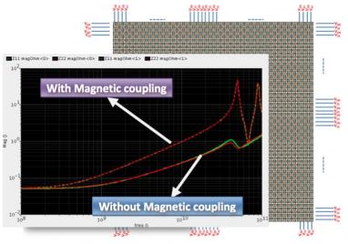
One possible solution: Helic’s VeloceRaptor/X™tool was used to model a medium complexity PDN (2 metal layers, occupying 1mm x 1mm total area with ~2000 via transitions per net) in a 28nm CMOS node. VeloceRaptor/X is the industry’s highest capacity extraction tool for high frequency and RF design. RLC and RLCK models were extracted for the PDN and the resulting impedance were compared over a wide frequency range. The PDN layout and impedance plots for the RLC/RLCK (i.e. without/with magnetic coupling) scenarios are shown below. It is clearly shown that magnetic coupling has a significant impact on the PDN impedance characteristic beyond 1 GHz. Therefore, for high-speed and high frequency design in GHz range, magnetic coupling cannot be ignored anymore. A high-capacity extraction solution is needed to accurate model the PDN, so that a proper supply decoupling scheme can be subsequently designed.
HelicCTO Dr. Sotiris Bantaswill be at the TSMC OIP Forum this week. Prior to Helic, he was a Research Engineer with the Institute of Communications and Computer Systems of the National Technical University of Athens (NTUA) and was involved in the design of silicon RF circuits, high-frequency integrated filters and data converters in the course of EU-funded research. Working closely with leading European semiconductor companies during his research years, he developed a deep understanding of design automation needs which he later transcribed into Helic’s innovative EDA products. Sotiris is an engaging guy so please stop by the Helic booth and introduce yourself.


Podcast EP332: How AI Really Works – the Perspectives of Linley Gwennap