Electron blur, stochastics, and now polarization, are all becoming stronger influences in EUV lithography as pitch continues to shrink
As EUV lithography continues to evolve, targeting smaller and smaller pitches, new physical limitations continue to emerge as formidable obstacles. While stochastic effects have long been recognized as a critical challenge [1,2], and electron blur more recently has been considered in depth [3], polarization effects [4,5] are now becoming a growing concern in image degradation. As the industry moves beyond 2nm node, these influences create a perfect storm that threatens the quality of EUV-printed features. Loss of contrast from blur and polarization make it more likely for stochastic fluctuations to cross the printing threshold [3].
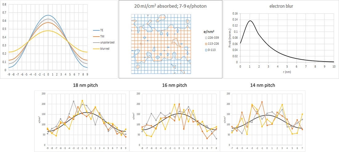
Figure 1 shows the combined effects of polarization, blur, and stochastics for 18 nm pitch as expected on a 0.55 NA EUV lithography system. Dipole-induced fading [6] is ignored as a relatively minor effect. There is a 14% loss of contrast if unpolarized light is assumed [5], but electron blur has a more significant impact (~50% loss of contrast) in aggravating stochastic electron behavior in the image. The total loss of contrast is obtained by multiplying the contrast reduction from polarization by the contrast reduction from electron blur.


Note that even for the 14 nm pitch case, the 23% loss of contrast from going from TE-polarized to unpolarized is still less than the loss of contrast from electron blur (~60%). As pitch continues to decrease, the polarization contribution will grow, along with the increasing impact from blur. As noted in the examples considered above, although polarization is recognized within the lithography community as a growing concern, the contrast reduction from electron blur is still more significant. Therefore, we must expect any useful analysis of EUV feature printability and stochastic image fluctuations to include a realistic electron blur model.
References
[1] P. de Bisschop, “Stochastic effects in EUV lithography: random, local CD variability, and printing failures,” J. Micro/Nanolith. MEMS MOEMS 16, 041013 (2017).
[2] F. Chen, Stochastic Effects Blur the Resolution Limit of EUV Lithography.
[3] F. Chen, A Realistic Electron Blur Function Shape for EUV Resist Modeling.
[4] F. Chen, The Significance of Polarization in EUV Lithography.
[5] H. J. Levinson, “High-NA EUV lithography: current status and outlook for the future,” Jpn. J. Appl. Phys. 61 SD0803 (2022).
[6] T. A. Brunner, J. G. Santaclara, G. Bottiglieri, C. Anderson, P. Naulleau, “EUV dark field lithography: extreme resolution by blocking 0th order,” Proc. SPIE 11609, 1160906 (2021).
Thanks for reading Exposing EUV! Subscribe for free to receive new posts and support my work.
Thanks for reading Exposing EUV! Subscribe for free to receive new posts and support my work. Pledge your support
Also Read:
Variable Cell Height Track Pitch Scaling Beyond Lithography
A Realistic Electron Blur Function Shape for EUV Resist Modeling
Rethinking Multipatterning for 2nm Node
Share this post via:


The Foundry Model Is Morphing — Again