Designing at 7nm is a big deal because of the costs to make masks and then produce silicon that yields at an acceptable level, and Silicon Creations is one company that has the experience in designing AMS IP like: PLL, Serializer-Deserializer, IOs, Oscillators. Why design at 7nm? Lots of reasons – lower power, higher speeds, longer battery life.
How about the challenges of designing at 7nm? There’s more analysis required, because of several factors:
- Circuit performance impact from parasitic RCL values increases
- Total number of RCL values increase
- Interconnect resistance slows down circuit propagation
- Coupling capacitors between adjacent interconnect affect circuit performance
- Circuit simulation times slow down with an increase in RCL values
- The BSIM-CMG model is more complex and thus slower than the previously used BSIM4 models using in SPICE circuit simulators
Pawel Banachowicz and Brian Eplett are engineers from Silicon Creations and they wrote a white paper on their 7nm IP verification experiences using EDA tools from Mentor – a Siemens business. This blog gleans what I found in their white paper.
For circuit simulation they used the Analog FastSPICE (AFS) tool because it provides them with:
- Up to 10X faster run times, using modern algorithms
- Optimization
- RCL reduction
- BSIM-CMG model support
- Transient noise analysis
- 120 dB of dynamic range
- 20M element capacity for full circuits with parasitics
- Multithreading support
Circuit designers know that silicon measurements are the ultimate reality, so the most important question then becomes, “Just how close are your circuit simulation results to measured silicon?”
Silicon Creations has their first 7nm silicon back from the foundry and it was successful on first-pass. The list of EDA tools they used during design and verification include:
- Circuit simulation for transient and full-spectrum device noise – Analog FastSPICE
- DRC and LVS – Calibre
- Parasitic extraction – xACT-3D
- Reliability verification – Calibre PERC
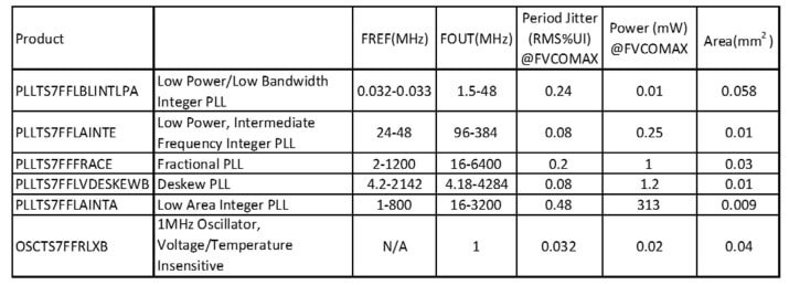
Their first six products to use 7nm silicon are listed below:
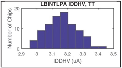
PLL Current Distribution
Phase noise correlation data shows that in their PLL design (PLLTS7FFLBINTLPA) with a 10 uW 32kHz input reference to 48MHz output, simulation predicted a current distribution mean of 3.02uA with a standard deviation of 1.5%, while measured silicon showed a mean of 3.15uA and standard deviation of 1.6%:
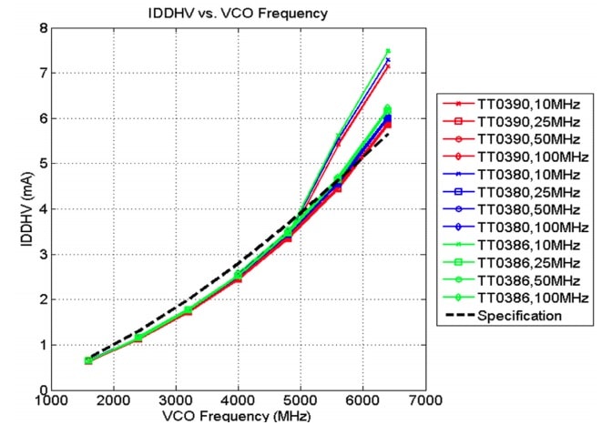
PLL Power Consumption vs Noise
Another PLL design (PLLTS7FFFRACE) met their performance goals of power consumption and noise as shown below where the specification is shown as a dotted line, then silicon measurements use colored lines:
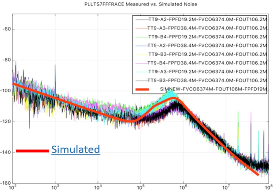
For the same PLL let’s look at measured versus simulated phase noise (red), another good correlation:
PLL Startup Behavior
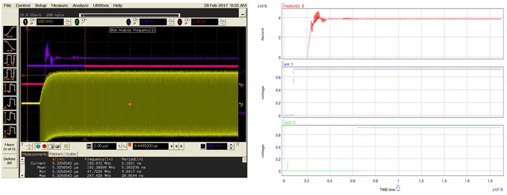
A low-power option Integer PLL (PLLTS7FFLAINTE) operates from a 24 to 48MHz input reference then has an output frequency ranging from 96MHz to 384MHz, and the measured (left) results are matched well by the simulated (right) values during startup:
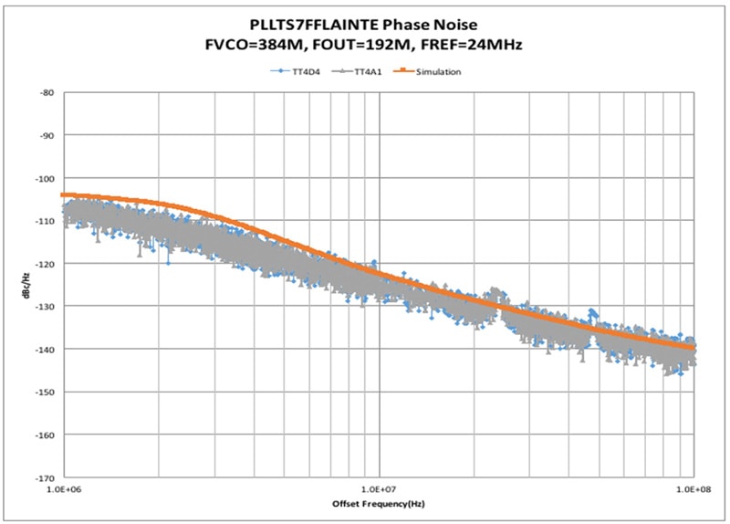
Looking at phase noise versus frequency for this PLL the simulated value (red) matches the measured values quite closely again:
Oscillator
Circuit designers want the oscillation frequency to be insensitive to both the power supply voltage and ambient temperature. The next two comparisons show simulated values (red) versus measured values (blue) for an oscillator (OSCTS7FFRLXB) design:

Conclusions
Kudos to the engineers at Silicon Creations for continuing to design AMS circuits down to the 7nm node and get first-pass silicon success. By using the AFS circuit simulator and other EDA tools from Mentor this company has a design and verification approach that produces accurate noise analysis results that are within 1dB to 2dB of measured results.
To read the complete 7 page White Paper visit this page at Mentor’s site.
Related blog – Device Noise Analysis, What Not to Do for AMS IC Designs
Share this post via:


Comments
There are no comments yet.
You must register or log in to view/post comments.