

My usual practice when investing is to look at startup companies and try to understand if the market they are looking to serve has a significant opportunity for a new and disruptive technology. This piece compiles the ideas that I used to form an investment thesis in Portable Stimulus. Once collected, I often share ideas to get feedback. Please feel free to offer up suggestions and critique. Thanks – Jim
The publication of Verification 3.0 was seen by many an evolution of existing functional verification methodologies.
It is far more than that. It is not just about a new tool, or a few extensions to existing tools: it is the start of a fundamental change in semiconductor development. Verification 3.0, and in particular verification synthesis, is a profound change that will sweep through the semiconductor industry, changing tools, flows and methodologies almost everywhere it touches.
The slowdown of Moore’s Law, or its irrelevance in some markets, means that design teams must focus on different aspects of a design than they used to. They cannot use scaling as the mechanism to provide the necessary gains and must look at architectures and optimizations more than in the past. Guard-banding and design for worst-case conditions often result in designs that are not competitive.
We see a slow transition for EDA tools to use more dynamic analysis. For example, power estimation was once based on statistical calculations, such as average switching rates. These methods were highly inaccurate and as power became more important, dynamic vectors had to be used to drive power estimation. Performance is another area, where the interaction of multiple independent threads of operation means that latency and throughput can no longer be calculated in a static manner. True usage scenarios have to be run.
Where do those scenarios come from? Without having scenarios defined, architectures cannot be analyzed, and informed decisions are not possible. The creation of these scenarios is often a slow, tedious, manual process that can only be utilized with one particular abstraction of the design and executed using only one simulator.
Existing Verification 2.0 methodologies, such as those based on the universal verification methodology (UVM), represent an isolated act of verification during a specific place in the development flow. They do not scale and are unable to migrate throughout the development flow. They also cannot be used at the system level where software becomes an important aspect of functionality.
This increases the verification task to include something we call Design Integrity.
Design Integrity suggests a more holistic view of a product-ready design. Depending on the industry segment it serves, it includes correct functionality compared to the specification, operational infrastructure including performance, power consumption and so forth. It is reliable to the level that an internal malfunction will not cause the design to fail and secure, not allowing malicious interference.
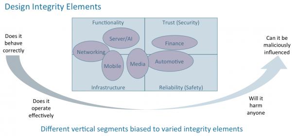
Figure #1: Different vertical segments have different design integrity requirements.
Source: Dave Kelf Consulting
A foundational piece of the Verification 3.0 framework –– verification synthesis –– will become the de facto source of those scenarios and will automatically generate necessary testcases that drive multiple execution engines. This technology utilizes a verification intent model written using the recently standardized Portable Stimulus Standard (PSS) from Accellera.
With adoption of the verification intent model, the design flow morphs from one where design is followed by endless verification into one where verification starts first.
The design integrity model is a tangible step toward an executable requirements document that will drive the entire design process from early virtual prototypes, to real silicon operating in the field and everything in between. It is a model independent of the implementation and agnostic about the point in the development flow.
Verification 3.0, anchored by the design integrity model, starts to align the development methodology to best practices developed by the rest of the industry. This will improve predictability in the development flow because important aspects of the product are verified first, rather than being left until later stages where system verification problems are discovered now.
Importantly, it creates a bridge between hardware and software development flows, allowing a controlled phasing of hardware/software integration. Taking this a step further allows for the concept of the digital twin to be created that can exist across multiple levels of abstraction and still maintain a single view for verification.
Having painted this broad picture of the size and scope of the disruption that caused by Verification 3.0, it is necessary to bring it down to earth. Let’s look at what is possible today, some of the issues associated with verification synthesis, and limitations of the initial Portable Stimulus Standard.
Defining Verification
Verification is a process of ensuring that an implementation matches a specification. With the exception of trivial designs, verification is an incomplete process because it is never possible to visit every possible state that a design of any reasonable size can be in, and to verify that under all conditions it does the right thing. This fundamentally defines the three things required of a verification strategy:
- Stimulus –– the ability to drive vectors into a design to get it into a particular state
- Checking –– ensuring that the right things happen to the design as stimulus is applied
- Coverage –– keeping track of which aspects of a design have been verified
In addition, bugs in the design, verification environment or the specification lead to failures that need to be analyzed and resolved. This process has to be intent driven.
Not all tools sold on the market as verification tools actually perform an act of verification. For example, a functional simulator only executes a model of the design that reacts to stimulus supplied on its inputs. The same goes for emulation. Tool suites have been constructed that add the ability to perform checking and to track coverage. Unfortunately, they were not designed into a complete methodology.
As a result, verification teams must learn multiple languages –– SystemVerilog is multiple languages that share a superficial, syntactic wrapper, for example –– and those languages do not naturally integrate into flows. Another example is when a user wants to attack a coverage hole. He or she has no way to relate that information into what has to be done with constraints to ensure that the right stimulus gets created. In addition, since there is no association between coverage and checking, marking off a coverage goal is not necessarily associated with an act of verification. This makes coverage closure a tedious and potentially error-prone process.
What’s in a Name
We have to address the name Portable Stimulus because it is a misnomer. The name came about because Accellera was already working on SystemVerilog and UVM, a language and library to support existing verification flows. Some enlightened industry experts recognized the limitations of this methodology and wanted to standardize a new methodology based on graph-based techniques.
Some in the standards community realized that they would not be able to get Accellera to work on a competing standard reframed the purpose of the new standard’s development. When the existing methodology was defined, there was only one class of execution engine –– the simulator. Simulators are flexible pieces of software that can easily adapt to different tools and languages being placed around them. However, simulator performance has not been able to keep up since computers transitioned from single core, to multicores. As designs got larger, simulator performance remained essentially flat and thus run-times exploded.
Because of this limitation, an increasing number of companies started to invest in emulation technology, specially designed machines that can perform design model execution orders of magnitude faster than simulators. Unfortunately, they do not have the same level of flexibility/adaptability, and all of the stimulus created for simulators could not easily be migrated to emulators. This made it difficult to combine simulation and emulation into a unified verification flow adding cost in terms of dollars and time.
Thus, the desire to make it possible to migrate simulation stimulus to emulators was born and where the name Portable Stimulus came from, see Figure 2.
Figure #2: Portability Stimulus suggests portability across design flows, tools, projects and specializations. Source: Accellera
However, it is not stimulus that is portable, as we will explain shortly. Making only stimulus portable is of little value if checking and coverage are not incorporated into testbench portability. The only aspect of Portable Stimulus that is portable –– and even then, with limitations –– is a language used to define the verification intent model. That portability is between vendors so that users do not develop models that would lock them into a single vendor’s solution.
The reality is that this level of portability has not been obtained with the 1.0 version of the standard, and we will explain that in detail later.
Now, it should be said that creating a standard takes effort. The initial offering is always missing key pieces. Over time, it will evolve. I always support standards because it will lower the cost of creating and implementing a methodology. The tool developer can concentrate on adding differentiating technology and not be burdened with the foundational elements now shared in the community.
It is from a Design Integrity Model that a suitable tool can synthesize stimulus, checks and coverage for several target platforms, including simulation and emulation. When vendors talk about their Portable Stimulus solution, they are talking about their verification synthesis capabilities. While a designer wants to ensure that they support every capability of the standard, it is quality of results that is more important. This is the same for high-level synthesis vendors. Designers need to know that they can accept the necessary input language, but that is a single item to be checked off in the evaluation. Most of the time is spent evaluating the capability and flexibility of the tools and the quality of results. This will become even more important as PSS vendors add capabilities such as AI to their synthesis engines to optimize and anticipate design verification requirements,
Value of Verification Synthesis
Having laid out the long-term impact that verification synthesis will have on the design flow, how does it provide immediate value that a designer needs in order to invest in the transition. To answer that, we look at the general approaches used by a UVM methodology and a verification synthesis methodology. Consider the design to be a piece of string. The more complex the design, the longer the piece of string.
Constrained Random Test Pattern Generation, the core technology embedded in SystemVerilog and UVM, works by randomizing inputs in the hope of hitting all possible outcomes. This is like wiggling one end of the string hoping that the other end will move in a meaningful manner. When it does, the design looks to see if it did the right thing. This might work for small designs, but quickly became so inefficient that changes had to be made.
That change was the creation of sequences, stiffening a segment of the string increasing the chances that the test would do something useful. It worked for a while, but highly inefficient. This analogy doesn’t even begin to extend to systems with multiple threads of execution that would mean multiple strings with ties between them.
A verification intent model is based on graph-based mathematical principles, well tested in many industries including semiconductor design. Control flow, dataflow, Petri nets are just a few examples of them used within this industry. They share is a way to define complete paths between inputs and output.
A graph is solved from output to inputs. No stimulus is ever created for which the outcome is not known and the coverage it will provide established. This should be sending loud bells going off in any designer’s mind. If every scenario created by verification synthesis has value, then how much quicker could a designer achieve the same level of confidence in the design? Isn’t coverage in a way just what is your confidence level you will tolerate. In safety and security designs the error has to be near zero. I think as a result this confidence level will be compliance driven. More on this later when we talk about the market.
Mentor, a Siemens Business, did a study of its verification synthesis solution several years ago compared to a UVM strategy. It concluded that the new methodology required one-tenth the number of vectors to reach the same level of coverage. Now, just think about how much that would save a designer in simulation licenses or even more so –– emulator costs.
Verification costs are the largest and fastest growing cost for semiconductor design. We are not going to suggest that verification synthesis will reduce time and costs by a factor of 10, because we expect most teams will then want to do increasing amounts of verification and get to higher levels of confidence. What a designer will get is much better utilization of precious assets to take back control of the verification process.
Introducing the Design Integrity Model
A design integrity model captures the primitive capabilities of the elements of a design. The Portable Stimulus standard provides a language to define this model. Two flavors of the language are available, a domain specific language (DSL) and C++. The domain specific language provides some useful macro capabilities making descriptions more readable by eliminating some of the superfluous C++ language constructs. Anyone who is comfortable writing C++ can ignore the DSL.
A model is composed of primitive actions. All available actions for an arbitrary block, such as a DMA engine or a UART, are contained within a component. Each action has one or more exec code blocks, which define how to make that action happen in a particular execution environment. Examples of execution environments include simulation, emulation and real silicon.
Components do not have to be complete, neither does the design integrity model. As soon as the solver, part of the verification synthesis tool, can find a path through the model that satisfies a verification goal, the verification process can start. The model can be refined and expanded without affecting any verification already completed.
Actions can be bound to each by control flow, data flow, and resources. In addition, tools that run on this model may add additional types of binding.
Control flow, which can be partially specified, defines required sequences of actions. For example, it could require that two actions be performed in sequence or concurrently. An intermediate form is also possible where the tool can decide how they are scheduled.
Data flow is defined by named data objects provided by actions and what they need in order to execute. For example, if a block produces a data packet called A, it can provide that to any action that requires a data packet A on its input. A transfer mechanism can also be defined that adds to notions of control flow. For example, the data may be transferred through a buffer, or through a stream. A stream defines that data is consumed at the same time that it is produced and thus implies concurrent execution of producer and consumer.
Resources define limited resources in a system that may be required by actions. PSS 1.0 defines discrete resources, such as DMA channels, processor threads and others. Tools may add other, more complex constraints such as memory resources. Actions may request resources and will be blocked if those resources are not available.
Additional types of binding include path constraints. These would note that if a certain sequence of actions has been performed, then only this action is allowed. This goes above and beyond what is currently defined in the Portable Stimulus Standard but does not preclude portability. The model can still be ported just without the extra information. This layered information is done in a similar manner to UPF layering on top of an RTL model. Over time, more of these layers should be standardized.
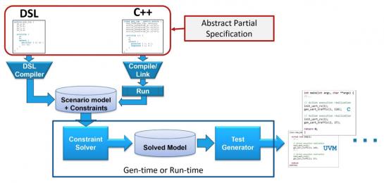
Figure #3: The PSS flow starts with one of two languages, either DSL or C++, that feed a specification through a compiler into a scenario model.
Source: Accellera
An Overview of PSS Tool Providers Today
At the time of writing this article, there are three main tool providers in this space with some additional companies taking an active part in the Accellera PSS committee. It should be carefully noted, however, that these tools are most definitely not created equal. Their approaches evolved from different needs and appear to contain different features for different purposes.
The three major PSS vendors offering a product right now are (in alphabetical order) Breker Verification Systems, Cadence Design Systems, and Mentor, a Siemens Business. Other EDA companies also involved in the committee, but are yet to introduce a product, include AMIQ, OneSpin Solutions, Synopsys, and Vayavya Laboratories.
Let’s take a quick look at the three PSS tool vendors today, based on publicly available information.
Breker Verification Systems
Breker has been an early supporter of this methodology for many years. Incorporated in 2003, Breker introduced a tool at that time that leveraged a C++ based, Portable Stimulus-like language for graph-based modeling that gained popularity among a few companies working on larger SoC platforms. Breker introduced its Trek product line with specific products to target SoC verification, UVM block-base verification and post-fabrication silicon bring-up or prototyping. Breker claims full support of the PSS standard, both C++ and DSL, and appears to focus on tool “deployment,” providing a complete path from PSS abstraction right down to UVM, SoC and post-Si testbenches.
Its website and other documentation note many features for ease of scenario modeling that work well with the standard today. They include a “Hardware Software Interface (HIS)” that provides a range of microkernel-like services to make SoC verification easier, memory allocation verification, test scheduling and synchronization synthesis, a test map debug viewer, virtual UVM sequence scheduling, and other capabilities. Breker provides a graphical entry tool and “Apps” for Cache Coherency, ARMv8 integration, Power Domain switching and its most Security app for an easy entry point to the solution that does not require learning PSS. Breker discusses advanced coverage analysis and closure, design profiling, and debug.
A founder of the Accellera Portable Stimulus standardization program, Breker donated a considerable amount of language capability. It has additional capabilities that may be layered onto standard models. They include Path Constraints and Path Coverage for scenarios models to be used to describe specifications, and those specifications to be configured for different verification scenarios, with coverage metrics that can be applied across the descriptions. Breker also has procedural modeling constructs that can layer onto standard models to provide enhanced modeling capability.
Breker publically notes eight significant semiconductor companies as users as well as a number of smaller ones on its website. Informative PSS use model case studies from a number of users are found on the website. Its tool seems to interface to various tools from all the major vendors and has a debug interface with the Synopsys Verdi debug environment. Breker’s website is: www.brekersystems.com
Cadence Design Systems
Cadence produced a tool in this area that attracted interest. In 2014 Cadence announced a product named the Perspec System Verifier, developed by the original Verisity team. Around the same time, it joined the Accellera PSS committee and donated new language features. In its product descriptions, Cadence highlights the portable nature of the tool, discusses an advanced solver (presumably based on the Verisity Specman technology), and notes a UML-like language platform. It produced an attractive user interface that allows scenarios to be graphical constructed and shows the results of the solved graph.
Documentation talks about generating tests for different environments and seems to rely on the end-user to create fundamental interface components that other tools vendors provide. For example, an HSI layer or other lower-level specific test generation capability is discussed. The end-user creates “exec-blocks” in its PSS descriptions that contain the C or SystemVerilog code to be written out with little help beyond solving the random elements of the graph itself. It appears Perspec is more focused at the SoC level than other areas of the verification process.
Cadence discussed the formation of an open source library of components, although no other public announcement has been made of this development. Cadence discusses working with the other Cadence verification tools, but no mention of working with third-party tool providers.
Debug and coverage mechanisms built upon its Indago and VManager tools have been mentioned. Cadence’s public material notes six significant semiconductor customers. Case studies can be found on its website. www.cadence.com
Mentor, a Siemens Business
Mentor was an early entrant in this area. In 2006, it acquired a company called Lighthouse that sold a tool called the inFact Intelligent Testbench. This has been rebranded Questa inFact and is now the current Mentor PSS tool. As a founder and active member of the Accellera Portable Stimulus standardization effort, it donated technology. inFact was initially targeted at the block or IP verification level. In addition, today Mentor discusses its usefulness at the SoC level.
From the public documentation, inFact appears to target the UVM block level rather than the SoC level. Mentor discusses test portability from block all the way to final silicon. It claims to be able to import elements of a UVM testbenches, and then integrate into the UVM sequence items to provide stimulus. Mentor talks about improved coverage closure at the block level and faster test creation with no mention of graphical editing tools, apps, libraries or other similar capabilities.
Mentor addresses inFact integration with other Mentor verification tools and does not note integration with third-party tools. Two joint customer papers were delivered in conferences. Mentor’s website is www.mentor.com.
Value Proposition
Having discussed the basics of the technology and the tool providers, the focus of the second part of this thesis will shift to the value propositions for users. Ultimately, the success of the technology will be decided by the value it provides. In the verification space, value is measured by issues such as:
- how quickly a team can gain confidence that a product will work as intended
- how efficiently it makes use of available compute capabilities and licenses
- how productive it makes the verification team
In addition, there are some other considerations not part of the verification process , such as:
- how to create a verification flow that spans the whole design process
- how to ensure that the most critical bugs are found first
- how to fully incorporate emulation, prototypes and real silicon into a verification flow
This and more will be covered in part 2.
Comments welcome.
Share this post via:


Podcast EP357: How Gonka is Changing the Way AI is Accessed with David Liberman