

By Jason Liu, RFIC-GPT Inc.
Radio frequency integrated circuits (RFICs) have become increasingly critical in modern electronic systems, driven by the rapid growth of wireless communication technologies (5G/6G), the Internet of Things (IoT), and advanced radar systems. With the desire for lower power consumption, higher integration, and enhanced performance, the complexity of RFICs has escalated correspondingly.
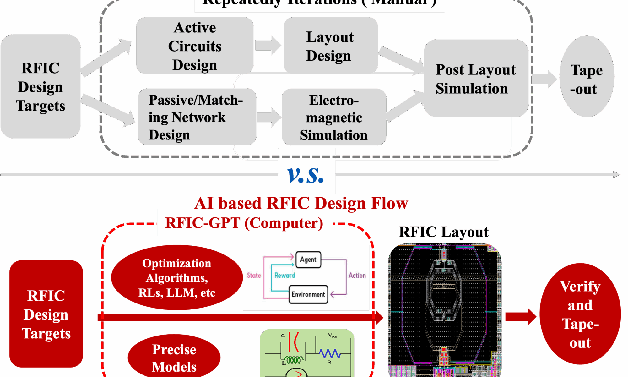
The design of RFICs is considered to be one of the most challenging areas in IC design due to the frequency dependent parasitic effects and time-consuming simulations, particularly the electromagnetic (EM) simulations. Till now, RFICs design remains heavily reliant on the expertise and intuition of specific experienced designers, requiring numerous iterative tuning and manual optimizations due to the nonlinear interactions between active and passive circuits. Conventional design flows, illustrated in the top half of Fig. 1, tend to be time-consuming and inefficient. Therefore, exploring efficient and automated methodologies to streamlining the RFIC design while ensuring optimal performance has become a key focus of research and industry. Here we introduce an AI-enabled automated design flow of end-to-end RFIC synthesis framework, integrating multiple precise modeling and optimization algorithms. As shown in the bottom half of Fig. 1, this process enables automated circuit synthesis of a DRC/LVS clean layout including placement and routing. Compared to traditional manual design flows that require repeated iterations between circuit design, layout, and EM simulation, the proposed approach enables efficient exploration of the extensive design space, which is one of the most significant challenges in design automation.

The overall framework of the proposed automated RFIC design flow is depicted in Fig. 2. This methodology is organized into three stages: circuit topology selection and specification definition, parameter optimization, and layout synthesis, with each stage being tightly integrated. The proposed flow begins with the selection of an appropriate circuit topology and the definition of key performance specifications, which should meet the functional requirements. For automation, the specifications are formalized into quantifiable targets and boundaries, which systematically guide the parameter optimization process and enables thorough exploration of the solution space, ensuring that the circuit satisfies all required standards.

The second stage of the automated flow is circuit parameter optimization based on the collaboration of multiple optimization algorithms, which includes various black-box optimization approaches. A black-box problem refers to an optimization scenario where the internal structure of the objective function is unknown and only its output for given inputs can be observed. Black-box optimization algorithms are designed to efficiently optimize such functions, especially when evaluations are costly, by adaptively selecting evaluation points. RFIC design inherently involves strongly coupled, nonlinear, multi-objective trade-offs (e.g., NF, gain, matching, linearity, power, and area) over a high-dimensional design space. These characteristics make RFIC design a typical black-box optimization problem, well-suited for advanced algorithms such as BO, genetic algorithms (GA), particle swarm optimization (PSO) etc. The final stage of the automated design flow of RFICs focuses on layout synthesis. Once the circuit parameters are optimized, the corresponding schematic is automatically translated into a physical layout using parameterized cells in conjunction to the optimization results. Placement and routing are subsequently performed within a RL-based Actor-Critic proximal policy optimization (PPO) framework, where the state is defined by the position and orientation of each device, the action corresponds to the movement direction and distance for the next placement step, the reward function is designed to optimize key layout metrics such as area utilization and density. Once the placement is finished, routing is performed by algorithm that efficiently determines the shortest path for signal wires while avoiding layout rule violations. The detailed algorithms of place and route will be presented in the future work.
To demonstrate the viability and effectiveness of the proposed automated design flow, it is applied to two different LNAs in 40-nm CMOS technology: a 2.4 GHz differential Cascode LNA and a 5.5 GHz two-stage differential CS LNA. For the first case, the automatically generated schematic and layout are presented in Fig. 3, where two transformers are used for input and output matching networks.

The cross-couple capacitor structure is introduced to neutralize Cgd, enhance gate-drain isolation and reduce nonlinear distortion. This example features a design space of 18 design variables and 7 optimization objectives. By applying the proposed automated design flow, circuit and layout (DRC/LVS clean) synthesis are accomplished within minutes. Fig. 3 shows the synthesized layout of the proposed differential cascode LNA, which occupies a die area of 0.38 × 0.94 mm2. Fig. 4 illustrates the post-simulated NF and S-parameters as well as the pre-simulated results, all specifications are satisfied. The post-simulated S21 of the proposed LNA shows a 3-dB bandwidth of 2 GHz to 2.7 GHz. The detailed simulation results are compared between pre-layout and post-layout simulations, revealing slight differences.


A 5.5 GHz two-stage differential CS LNA is also generatively designed within a couple of minutes, where the generated schematic and layout are shown in Fig. 5, in which three transformers implement the input, interstage and output matching networks while the cross-couple capacitor structure is applied to each CS stage. This architecture introduces approximately ten additional design variables (26 in total), substantially expanding the design space and increasing optimization complexity. As shown in Fig. 6, both pre- and post-simulated NF and S-parameters meet the targets. The Table in Fig. 6 shows close agreement between the pre- and post-simulations.

Finally, an automated design flow of RFICs based on various AI models and algorithms is presented. Moreover, this design flow has been impletemented in RFIC-GPT, a tool readily to be tested online: https://rfic-gpt.com/ .
Also Read:
Propelling DFT to New Levels of Coverage
AI-Driven DRC Productivity Optimization: Insights from Siemens EDA’s 2025 TSMC OIP Presentation
How PCIe Multistream Architecture Enables AI Connectivity at 64 GT/s and 128 GT/s
Share this post via:


Musk’s Orbital Compute Vision: TERAFAB and the End of the Terrestrial Data Center