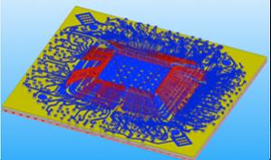

 Power delivery networks (PDN) are the metal structures on a chip that delivers the power. In a high-end desktop SoC this might be delivering as much as 150W, and with voltages around 1V that means over 150 amps of current. Clearly getting the PDN correct is critical for a correctly functioning chip. One of the challenges to verifying the PDN is that early in the design the precise circuits are not finalized, and no vectors are available to perform the verification.
It is no longer possible to simply over-design the PDN since chips are increasingly routing area-limited. Instead, there is a requirement to efficiently perform PDN verification to ensure that all the currents and terminal voltages remain within specification, and that the line currents remain within limits protecting the grid from reliability issues.
The traditional approach to power grid verification is power grid analysis (PGA), which employs circuit simulation to check the grid voltages and currents in response to a current stimulus that represents the pattern of activity of the underlying circuit. The current stimulus ideally is the result of multiple simulation runs of the underlying transistor circuit, but that technique is prohibitively expensive. The more practical (and typical) approach is to generate the current stimulus based on specific workload scenarios (operational modes) of the underlying circuit.
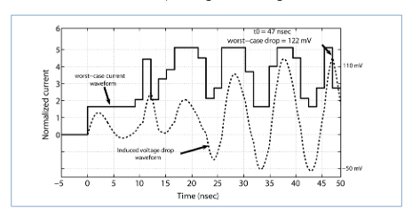
Because of this need for a current stimulus, power grid analysis suffers from certain limitations. Naturally, to guarantee safety and reliability under all conditions, designers are interested in worst-case behavior on the grid, yet there is no known method for finding the true or realistic worst-case behavior without an exhaustive analysis, which is prohibitively expensive. In the real world, designers are reduced to generating the current stimulus based on typical or representative workload, neither of which are easy to define and, in any case, are insufficient to guarantee grid safety under all conditions. In fact, typical case analysis only provides a lower bound on the true worst-case voltage or current variations on the grid. To make things worse, it is extremely important to perform some type of grid verification during early design planning, but information on circuit workload is often simply unknown early in the design flow.
Existing power grid analysis, then, effectively shifts the burden onto the designer, who is required to provide the workload patterns for which the grid will be verified. A superior approach would obviously not burden designers to this extent. That is the promise of vectorless verification—a verification that does not require any user-input stimulus.
However, this notion of a truly vectorless verification approach is simply impossible to realize. Given any power grid that presumably has been checked and verified by such a hypothetical engine, designers can always envision an underlying circuit that would draw a large enough current to make the grid unsafe. We will never have an ideal vectorless verification approach for the power grid.
Given, then, that power grid verification must require some information about the current stimulus, the burden is on EDA developers to minimize the amount of information required. We describe an approach that aims to achieve this goal. Such an approach is not computationally cheap, but it gives a good upper bound on the true worst case, and it holds the promise of leading to practical approaches for certain scenarios, especially for early design planning.
One simple case is to assume all the currents are DC, also known as static verification. Only the grid resistance is relevant and the voltage drops can be calculated.
 The problem is much harder in the dynamic case, where transient currents are allowed and RLC parasitics all become relevant. Exact solutions become prohibitively expensive, and we see that bounds on the solution must be sought for practical use. The constraints remain DC, but all current and voltage signals are transient over time.
Mentor have a new white paperVectorless Verification of IC Power Delivery Networks which covers the topic in a lot more detail. The author is Farid Najm of University of Toronto. It can be downloaded here
More articles by Paul McLellan…


Comments
There are no comments yet.
You must register or log in to view/post comments.