


In the world of IC testability we tend to look at various approaches as independent means to an end, namely high test coverage with the minimum amount of test time, minimum area impact, minimum timing impact, and acceptable power use. Automatic Test Pattern Generation (ATPG) is a software-based approach that can be applied to any digital chip design and requires that scan flip-flops be added to the hardware. SoCs can also be tested by using on-chip test hardware called Built-In Self Test (BIST).
At the ITC conference this week there’s news from Mentor Graphics about a hybrid approach that combines both ATPG and BIST techniques. Ron Pressand Vidya Neerkundar wrote a seven page white paper, and I’ll summarize the concepts in this blog. Read the complete white paper here or visit Mentor at ITC in booth #211 and ask for Ron or Vidya.

Ron Press
ATPG
The basic flow for using ATPG and compression is shown below:
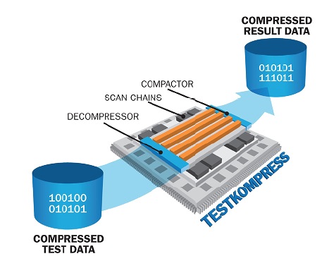
The ATPG software is first run on the digital design and patterns are created that will be applied to the chip primary input pins and read on the output pins. To economize on tester time compression is used on both the incoming and outgoing patterns. Extra hardware is added to the chip for decompression, scan chains and compression. Benefits of using compression ATPG are:
- High fault coverage for stuck-at and other faults (ie. resistive, transistor-level)
- Low test logic overhead
- Low power use
Logic BIST
With Logic BIST the chip itself includes the test electronics and instrumentation.
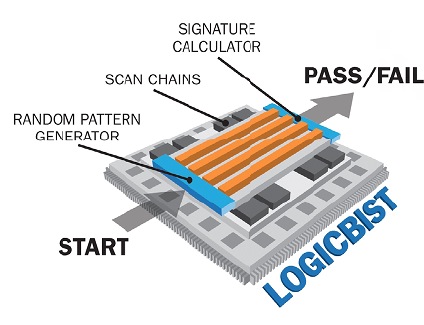
The test electronics is shown as a random pattern generator with a blue color on the left. The instrumentation to measure results is called a signature calculator with a blue color on the right side. Scan chains are shown in orange color, just like in the previous diagram for ATPG. The Random pattern generator is creating it’s own stimulus, which is then applied to the block under test. The response to the stimulus is collected by the signature calculator to determine if the logic is correct or defective. Benefits of using a logic BIST approach are:
- No need for an external tester
- Supports field-testing
- Can detect un-modeled defects
- Support design re-use across multiple SoC designs
- Reduces tester times because you’re not limited to reading external data
Comparing ATPG and Logic BIST
Let’s take a quick comparison overview of ATPG and Logic BIST to better understand where each would offer the greatest test benefits.
[TABLE] style=”width: 500px”
|-
|
| ATPG
| Logic BIST
|-
| Black-box module
| OK
| Not accepted because of potential unknown, or X values
|-
| Testpoints
| Required less
| May be required for some faults
|-
| Multi-cycle paths
| Supported
| Added hardware required
|-
| Cross Domain Clocking
| Easy support
| Unknown states cannot be captured
|-
| ECO support
| Easy
| Masking ECO flops adds hardware
|-
| Diagnostic resolution
| Good
| Good
|-
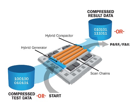
The Hybrid Approach
There is a way to combine test hardware so that any block can have both compression ATPG and Logic BIST approaches together:
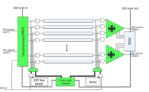
Diving into a bit more detail reveals some of the test logic in the hybrid approach:
With a hybrid implementation ATPG would only need to target faults that are not already detected by Logic BIST, saving test times up to 30% or so. You can use this hybrid methodology in either a top-down or bottom-up flow.
Hybrid Benefits
Adopting a hybrid test approach can provide:
- Test/retest SoCs during burn-in and in-system
- Very low DPM (Defects Per Million)
- Checks for many defects
- Small delay
- Timing-aware
- Cell-aware
- Path delay
- Lower test hardware area through merged logic
Summary
It may be appropriate to consider using both compression ATPG and Logic BIST in your next SoC design. Mentor Graphics offers software named the Tessent product line that support hybrid test. Read the complete white paper here, registration is required to download the PDF document.
lang: en_US
Share this post via:


TSMC CoWoS versus Intel EMIB Semiconductor Packaging