I was kind of shocked when the service manager at our local VW dealership told me that one of the wires in the ignition system of my wife’s New Beetle had started to overheat, melting the insulation and becoming a safety hazard. Why didn’t a fuze just blow, protecting the wiring from overheating? We decided to quickly sell that car and made a mental note to double-check with Consumer’s Report before buying another vehicle with electrical issues. Most of us drive a car and often I just take it for granted that the electrical wiring is OK, expecting that some engineer has tested out the complex system before actually building production units.
Automotive companies can use a methodology of selecting wires that are larger than needed for the actual load, then building prototypes in order to measure currents and finally determine how to protect wires with a fuze. A more modern approach is to model and simulate the wiring for a car, although it’s a challenge when each make and model of car has a variety of trim packages and electrical options. Analyzing your automotive wiring during the design phase requires that you design different by:
- Entering accurate load information for all devices that draw current (motor size, Volts, Amps)
- Knowing the current flow through Engine Control Units (ECU’s)
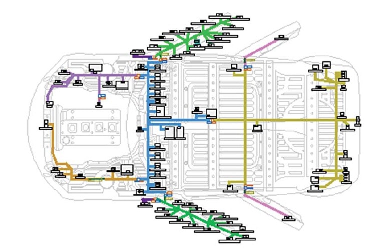
- Modeling the entire electrical architecture of the vehicle with component locations, relative temperatures, and the harness interconnect points
- Have accurate models for the battery, fuses, wires and basic discrete devices

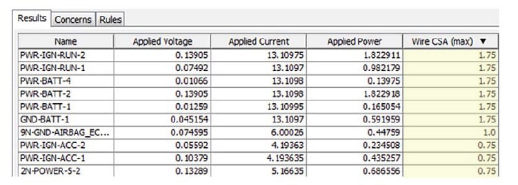
Engineers at Mentor Graphics have created automation tools to help automotive designers in this area, and a full analysis can be run that produces a table showing the recommended wire size (CSA max):

Knowing the proper wire sizes before production is a much smarter way than building a prototype and measuring because it saves both time and money. Recalls in the automotive industry can be quite costly and embarrassing to the brand.
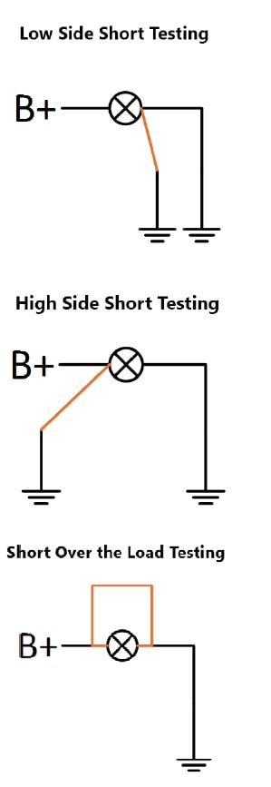
Fuses should protect against accidental shorting, and there are three types of short circuit test cases:

If you build a physical prototype and run this type of short testing (aka Wire Smoke Testing) for all electrical loads in a car it will take lots of time and engineering effort. Then you have to check for fumes caused by wires that are over-loaded, heating up and burning the insulated coating.
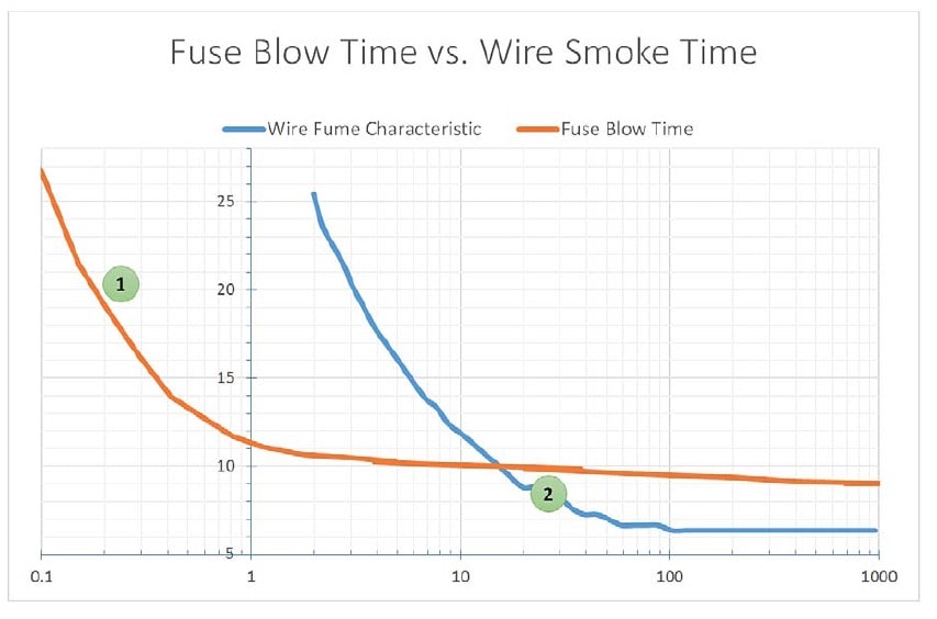
Knowing the characteristics of wire fumes (blue line) and the fuse blow time (orange line), we can start to get a bit more scientific about wire sizing and fuses.

The Y-axis is Amps and the X-axis is Seconds. At point 1 the fuse will blow first at about 20 amps (orange curve), which is desirable. However, at about 8 amps show as point 2 the wire will be fuming before the fuse blows, and that’s a big problem.
Summary
Automotive wire harnesses must be designed for safety, and now there’s an automated approach that can be used during the design process to ensure that the current loads of each wire do not damage the insulation, and that the proper fuse values are selected, giving us electrical protection. Mentor Graphics has been involved with cabling design systems for many years now, and Mike Stamper has written a White Paper on this topic:
Related blogs:
- Mentor: It’s All About Cars
- Open Source Software Platform Fuels Automotive Innovation
- Increasing Automotive Semiconductor Test Quality
- The Best Conversations You Missed at #52DAC


Comments
There are no comments yet.
You must register or log in to view/post comments.