One year ago the annual share holder meeting at Mentor Graphics had tight security, a no-camera policy, and the drama of Carl Icahn the corporate raider successfully adding three new board members. Fast forward to today where two of Icahn’s board members were not even nominated, and Mentor added two new board members. I chatted with Keith Barnes after the meeting and he has a solid background in EDA, test and semi.
Keith Barnes
Keith Barnes is Chairman of Verigy US Inc., a Cupertino-based company that designs, develops and manufactures advanced test systems and solutions for the semiconductor industry. From 2003 through 2006, he was Chairman and CEO of Electroglas, Inc., having been brought in by the board to execute a turnaround of the manufacturer of integrated circuit probers. Prior to that he was Chairman and CEO of Integrated Measurement Systems, a leader in digital, mixed-signal and memory-IC verification, until its acquisition by Credence Systems Corporation in 2001. Before assuming his role at IMS, Mr. Barnes was a division president at Cadence Design Systems and at Valid Logic Systems. Just three years after earning his degree in Environmental Studies at San Jose State, he co-founded Kontron Electronics, Inc., which was acquired by BMW in 1985.
Mr. Barnes has served on numerous boards and industry associations during his career, including three terms as a regent of University of Portland. He is currently on the board of Cascade Microtech, Inc. He is an inaugural member of the College of Social Sciences’ Dean’s Circle and spoke on campus in November 2008 as part of the Alumni Association’s Alumni Legends Speaker Series.He and his wife Sharon have three children and live in Portland, Oregon.
Daniel McCranie
Since August 2002, Mr. McCranie has served as Chairman of the Board at Freescale Semi and since November 2001 as a Director of ON Semiconductor Corporation, a supplier of high performance silicon solutions for energy efficient electronics. From October 2008 to September 2010, Mr. McCranie served as Executive Chairman of Virage Logic, a provider of application optimized semiconductor intellectual property platforms. Previously, Mr. McCranie served at Virage Logic as President and Chief Executive Officer from January 2007 to October 2008, Executive Chairman from March 2006 to January 2007, and Chairman of the Board of Directors from August 2003 to March 2006. From 1993 until his retirement in 2001, Mr. McCranie was employed in various positions, including as Executive Vice President, Marketing and Sales, with Cypress Semiconductor Corporation, a supplier of diversified, broadline semiconductor products, focusing on the communications industry. Mr. McCranie has been a member of the board of directors of Cypress Semiconductor since February 2005. From April 2004 to October 2010, Mr. McCranie served on the board of directors of Actel Corporation, a designer and provider of field programmable gate arrays and programmable system chips. From 1986 to 1993, Mr. McCranie was President, Chief Executive Officer and Chairman of SEEQ Technology, Inc., a manufacturer of semiconductor devices. In addition to On Semiconductor, Cypress Semiconductor and Virage Logic, within the past ten years, Mr. McCranie has served on the board of directors of Xicor, Inc., Actel Corporation, ASAT Holdings, California Microdevices and Actel Corporation.
Shareholder Meeting
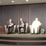
Wally Rhines started the meeting promptly at 10AM and the formal part of the meeting was completed in just 5 minutes. Dean Freed presented the share holder introductions and noted that:
- 102 million shares voted this year
- 93% of shares voted
- A quorum of voters was present or represented
All four matters up for vote were accepted:
[LIST=1]
Two new board members.
New compensation plan for executives.
Executive variable incentive pay plan continued.
KPMG as the official accounting firm.
Wally thanked Jose Maria Alapont and Gary Meyers for their board service, now that is a classy goodbye for two former board members.
EDA Presentation
Wally had a handful of slides to overview what EDA is all about. Some nuggets I found:
- Revenue by divisions: PCB 15%, Verification 30% (ModelSim), IC Design to Silicon 40% (Calibre, IC, DFT), New 10% (embedded), Services 5%
- Customers: 50% Semi, 50% Systems
- PCB market share of 44% in 2012, up from 20% in 2000 (per Gary Smith EDA numbers)
- Calibre started in 1996 at just $1.1M revenues, now at $300M the dominant DRC/LVS tool
- Emulation – could be a new discontinuity opportunity, full chip verification requires emulation.
– Customer example of a 10 million gate SOC for a digital camera, 309 hours on compute farm, or just 20 minutes on Veloce emulator (800x speed improvement). 2010 at 36% and growing share. 10KW wow, competition has 40KW power. Veloce 2 has 2X the gate count, bookings are solid.
- Moore’s Law will not continue forever, 28nm node has widespread adoption now while shortages exist. Foundries have been spending 7B annually, however in 2010 it was $14B and 2012 at $17B to service 28nm, so capacity should become available soon. Intel will spend $12.5B, Samsng $13.1B, TSMC $8.5B, Hynix $3.1B.
- 32nm/28nm is fully loaded, at capacity now (yield and throughput is still low).
- Financial results – revenue with 9% CAGR. Friday reported $248M (highest), EPS $.30 (non-GAAP).
- 2013 outlook – 28nm/20nm adoption is strong. $240M in Q2, 12% increase. EPS of $0.17.
- 8% revenue growth to $1.1B in 2013. Faster than overall EDA growth rates.
- R&D about 30% of budget. Cash – repurchase shares, 6% bought last year, 200 million purchase this year.
Q&A
Q: Synopsys and Cadence both bought IP and Verification IP companies, will Mentor follow in this direction?
A: Mentor did invest in 1994, acquired, grew, then sold business. No plans to grow that market segment again.
Q: Do you have any concern about Chinese EDA competitors?
A: Mentor is the largest EDA supplier in China now, Korea and India. We’ve been succesfull in growing EDA in China. Piracy protection is always a concern.
Q: Synopsys and Magma comments?
A: Magma was a small player, we already compete with them, and didn’t want to participate in a bid for Magma.
Labor Union
A member from the local AFL-CIO read a prepared statement and recommend a no vote on board member David Schecter because he supports Icahn’s plan to sell the company. Labor does not not want Mentor to accept any offers from Ican to buy the company. (Applause)
Summary
I counted about 43 people in attendance today (about half of last years number) and the mood was upbeat and confident, quite the contrast with the takeover drama from last year. Wally Rhines is excited about the industry transition to 20nm and the research on 14nm, who knows maybe we will see EUV being used in production.
Mentor is poised to outperform the general EDA growth rate in calendar 2012 and the new board members should provide some positive industry insight.