You are currently viewing SemiWiki as a guest which gives you limited access to the site. To view blog comments and experience other SemiWiki features you must be a registered member. Registration is fast, simple, and absolutely free so please, join our community today!
Daniel is joined by Ajit Manocha, president and CEO of SEMI, the global industry association serving the semiconductor and electronics manufacturing and design supply chain. Throughout his career, Manocha has been a champion of industry collaboration as a critical means of advancing technology for societal and economic prosperity. He began his career at AT&T Bell Laboratories as a research scientist and was granted more than a dozen patents related to semiconductor manufacturing processes that served as the foundation for modern microelectronics manufacturing.
Ajit discusses his AT&T Bell Laboratories roots and the focus on “connect, collaborate, innovate” that the organization instilled. He explains that he found this same focus at SEMI, which drew him closer to the organization to become its president and CEO. Dan explores the substantial impact SEMI has on the semiconductor industry. Ajit describes broad coalitions between SEMI members, governments and academia to address key issues such as talent pool growth, energy reduction and reduction of harmful compounds such as PFAS. The collaboration with the United Nations and the EU is also described.
Dan explores future efforts of SEMI with Ajit that include AI data protection and cybersecurity.
The views, thoughts, and opinions expressed in these podcasts belong solely to the speaker, and not to the speaker’s employer, organization, committee or any other group or individual.
Non-volatile memory choices are becoming more complex as SoC designs push into advanced nodes, and new requirements driven by AI, new sensor technologies and stringent quality standards.
The second annual 2025 NVM Survey, completed in December, captures a market that still hangs on established technologies but is increasingly testing alternatives in response to these new design and production constraints.
More than 80% of respondents say they use or evaluate embedded non-volatile memory technologies. 20% are looking for an NVM now, and just under 30% expect to choose NVM IP within the coming year. Taken together, this points to a market that is both experienced and active. A meaningful proportion of near-term decisions are yet to be made, leaving a lot to play for among the competing technologies.
Fig. When do respondents plan to select an NVM
Embedded flash continues to dominate in terms of technology recognition, with awareness exceeding 80% of respondents, reflecting its long-standing role as the default choice. That said, the survey shows a broadening of familiarity beyond flash. FRAM, MRAM, and ReRAM are each recognized by more than a quarter of respondents, indicating that alternative NVM technologies are now part of mainstream awareness.
Vendor recognition follows a similar pattern. A small group of suppliers stand out in terms of familiarity, led by SST (embedded flash), Infineon (SONOS), and Weebit Nano (ReRAM), in that order.
When respondents were asked to weigh the importance of embedded NVM selection criteria, the results emphasize practicality. Reliability, endurance, and data retention all score at the top of the range, each with weighted averages well above 3.0 out of 4.0, confirming that they remain foundational requirements for embedded NVM selection. Process scalability follows closely, also scoring above the 3.0 mark, reflecting the growing difficulty of extending traditional embedded NVM into advanced geometries that embedded flash cannot scale to. Power efficiency scored over 3.0 too. Integration risk and long-term predictability sit only marginally behind, indicating that manufacturing readiness and lifecycle stability are now considered nearly as important as raw technical performance. This shows that the market is maturing; people understand that the raw technical capability of new NVMs is there, but the risk and cost of integration are becoming real concerns, especially for advanced nodes where flash integration is not an option.
The risk and pain-point data reinforce this view. Scalability limitations and power-performance trade-offs rank highest, both scoring with weighted averages above 3.0 out of 4.0, indicating that they are seen as critical constraints in current NVM deployments, especially in advanced process nodes. Reliability concerns and cost uncertainty follow closely behind, also clustering in the upper end of the scale, suggesting that long-term predictability and economic risk remain unresolved issues for many designs. Taken together, these pressures help explain why awareness of alternative NVM technologies is increasing, even where adoption remains cautious.
Fig. Pain points by importance
Design pressure seems to be increasing faster than legacy memory can adapt. What has changed since last year’s survey is not a collapse in confidence in embedded flash, but a clear acceleration in the pressures acting upon it. More teams are now evaluating alternatives not out of curiosity, but because scaling, power, and long-term predictability are becoming binding constraints on future designs.
Overall, the 2025 survey does not point to an abrupt abandonment of embedded flash, but it does suggest that the transition away from traditional memory technologies is entering a more decisive phase and might be likely to accelerate as design starts transition to nodes where new NVMs are required for technical reasons. Awareness of alternative NVMs is rising, evaluation is broadening, and a significant share of teams expect to make concrete IP choices within the next year.
Fig. Planned design starts by node
External forecasts point the same way: Yole Group’s outlook suggests embedded emerging NVMs could reach $3.3B by 2030, driven by adoption of technologies such as MRAM, PCM and ReRAM in next-generation MCUs and SoCs.
Compared with last year’s results, the direction of travel is clearer: the question is no longer whether embedded flash can be extended further, but how long it can continue to meet the combined demands of scaling, power efficiency, reliability, and cost predictability.
Bottom line: For many SoC teams, NVM selection is shifting from a background assumption to an urgent architectural decision that will shape product viability in the next generation of designs.
The global semiconductor market in 2025 was $792 billion, according to WSTS. 2025 was up 25.6% from 2024, the strongest growth since 26.2% in the COVID recovery year 2021. The increase was driven by AI, with Nvidia revenues up 65%. The major memory companies (Samsung, SK Hynix, Micron Technology, Kioxia and Sandisk) all cited AI as the primary revenue driver in their collective 29% revenue growth.
Fourth quarter 2025 results were mixed. The memory companies reported revenue growth in the range of 21% to 34% versus 3Q 2025. Nvidia was up 20%. Ten companies had 4Q 2025 revenue up in the range of 0.2% to 11%. Four companies (Texas Instruments, Infineon, Sony Imaging and Onsemi) reported revenue declines.
Guidance for 1Q 2026 revenue change from 4Q 2025 is mixed. The three memory companies providing guidance are expecting substantial revenue increases in 1Q 2026 with Micron at 37%, Sandisk at 52%, and Kioxia at 64%. Nvidia projects AI will drive 14% revenue growth. Four companies project revenue gains ranging from 2% to 11% based on a recovering industrial market and continuing AI strength. AMD, NXP Semiconductors, STMicroelectronics and Onsemi project revenue declines primarily due to seasonality.
The huge memory demand in AI is causing shortages of memory for other applications. Intel expects an 11% decline in revenue in 1Q 2026 versus 4Q 2025 due to shortages of memory for PCs. Qualcomm and MediaTek both cite memory shortages for smartphones as the reason for projected revenue declines.
In December, IDC cited the memory shortage as potentially leading to declining shipments of smartphones and PCs in 2026.
Thus, if strong AI growth continues in 2026, semiconductor companies dependent on the smartphone and PC markets could see revenues decline in 2026.
A year ago, no one predicted demand for AI would drive 25.6% growth in the semiconductor market in 2025. We at Semiconductor Intelligence give a virtual award for the most accurate semiconductor market forecast for the year. The criteria are publicly available forecasts released between October of the previous year and release of the WSTS January data in early March. The winner for 2025 is IDC which predicted 15% growth. Several other prognosticators were in the 12% to 14% range.
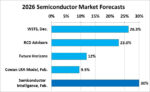
Looking ahead to 2026, recent forecasts are in two groups. In the lower group, the Cowan LRA model (based on historical revenue trends) has 9.5%. Future Horizons projected 12%. The higher group includes RCD Advisors at 23%, WSTS at 26.3%, and Semiconductor Intelligence at 30%.
We at Semiconductor Intelligence believe the robust expansion of AI will continue through at least the first half of 2026. The high quarter-to-quarter semiconductor market growth of 16% in 3Q 2025 and 14% in 4Q 2025 followed by an expected strong 1Q 2026 practically guarantees 2026 growth over 20%. Even if memory shortages impact the smartphone and PC markets, the booming AI market and the relative stability of the industrial and automotive markets will continue to drive semiconductor growth in 2026.
Semiconductor Intelligence is a consulting firm providing market analysis, market insights and company analysis for anyone involved in the semiconductor industry – manufacturers, designers, foundries, suppliers, users or investors. Please contact me if you would like further information.
As computing expands from data centers to edge devices, semiconductor designers face increasing pressure to optimize both performance and energy efficiency. Advanced process nodes continue to provide transistor-level improvements, but scaling alone cannot meet the demands of hyperscale AI infrastructure or ultra-low-power edge systems.
Synopsys Foundation IP enables SoC designers to customize their designs for specific application requirements, combining IP optimization with advanced EDA flows. Real customer engagements demonstrate how this approach improves power efficiency, reduces energy consumption, and unlocks system-level performance gains beyond standard scaling benefits.
Hyperscale Compute: Power-Efficient 2nm SoCs
One customer develops SoCs for hyperscale AI and cloud infrastructure, where compute density and power efficiency directly impact operational costs. Even at 2nm nodes, transistor scaling alone could not deliver the needed performance-per-watt improvements.
Synopsys collaborated with the customer to customize Foundation IP and integrate it with advanced EDA optimization flows. Standard cells were refined for transistor sizing and threshold voltages, while layouts were adjusted to reduce routing parasitics. These changes improved both energy efficiency and performance in dense compute blocks.
The result was meaningful reductions in power consumption and higher silicon utilization, demonstrating how hyperscale customers can extend the value of advanced-node technology while lowering system-level operational costs.
34% reduced power consumption over baseline (using baseline EDA flow)
51% reduced power consumption over baseline (using an optimized EDA flow)
5% silicon area advantage over baseline
Edge AI Devices: Ultra-Low-Voltage Operation
Another customer develops Edge AI devices that require always-on functionality and strict energy efficiency. Battery life, standby power, and thermal constraints are critical, and standard IP could not reliably operate at ultra-low voltages.
Synopsys helped redesign memory bit cells and peripheral circuits to maintain read/write stability under low supply voltage. Assist circuitry improved access reliability, while memory compiler updates reduced standby power without sacrificing performance.
Logic libraries were optimized using low-leakage transistor configurations, and multi-rail voltage strategies allowed memory and logic to operate at independently optimized voltages. Variation-aware modeling and silicon correlation analysis reduced conservative guard-bands, enabling further voltage scaling and energy reduction.
These optimizations enabled every part of the chip to consume less power and occupy less space, delivering longer battery life, improved thermal performance, and reliable always-on operation. The approach provides a repeatable framework for other Edge AI device manufacturers pursuing aggressive power efficiency goals.
Cross-Domain Engineering: A New Implementation Model
Both customer engagements highlight the value of cross-domain engineering, where IP design, EDA flows, and system-level architecture are optimized together. Coordinated optimization allows teams to evaluate performance and power across multiple layers of design and operating conditions.
This methodology helps uncover efficiency opportunities that traditional sequential design approaches often miss. It also reduces design risk, improves first-silicon success, and accelerates time-to-market. Customized IP can be reused across future designs, amplifying long-term return on engineering investment.
Delivering System-Level ROI
These customer engagements illustrate a broader industry trend: semiconductor return on investment increasingly depends on extracting value across the entire design stack, rather than relying solely on transistor scaling. For hyperscale infrastructure, customized IP helps reduce energy consumption, increase compute density, and lower operational costs, while for Edge AI devices, it enables ultra-low-voltage operation, extends battery life, and improves overall device functionality. In addition, reducing guard-bands and optimizing design margins further enhance manufacturing efficiency and strengthen product competitiveness. The techniques demonstrated through these engagements are transferable across similar market segments, providing a practical framework that allows both hyperscale and Edge AI customers to accelerate innovation and maximize performance-per-watt.
Summary
As AI workloads grow and edge intelligence proliferates, customized Foundation IP coupled with advanced EDA optimization will continue to be a key enabler of power-efficient, high-performance semiconductor design.
By combining cross-domain engineering with application-specific IP customization, Synopsys helps customers extend the benefits of scaling into system-level performance, energy efficiency, and economic gains across hyperscale infrastructure, Edge AI devices, and emerging intelligent computing platforms.
Akeana Inc. announced a key milestone in the development of its advanced RISC-V technology: a successful partnership with Axiomise Limited to formally verify its super-scalar test chip, Alpine. The collaboration highlights the growing importance of formal verification in ensuring correctness, performance, and efficiency in next-generation semiconductor designs.
Alpine is a 4nm silicon and software development board that integrates high-performance, out-of-order RISC-V cores. As semiconductor process nodes continue to shrink and architectural complexity increases, ensuring functional correctness before tape-out has become both more challenging and more critical. Super-scalar, out-of-order cores, designed to execute multiple instructions per clock cycle, introduce intricate control logic, speculative execution paths, and numerous corner cases that are difficult to fully validate using traditional simulation techniques alone.
To address these challenges, Akeana turned to Axiomise for its deep expertise in formal verification. Unlike simulation-based approaches, which rely on test vectors and probabilistic coverage, formal verification applies mathematical proof techniques to exhaustively analyze all reachable states of a design. This guarantees that specific properties hold true under every possible condition, eliminating entire classes of latent bugs that could otherwise escape detection.
According to Nitin Rajmohan, Co-founder of Akeana, the results of the engagement exceeded expectations. Within just a few months, Axiomise’s team not only identified functional issues but also uncovered potential redundant logic in the design—findings that were not anticipated at the outset. These insights provided Akeana with opportunities to further optimize its RTL before tape-out, reducing risk and improving overall design quality. The experience reinforced the long-term value of formal verification within Akeana’s broader development methodology.
Axiomise employs a structured methodology that combines expert consulting with proprietary applications such as formalISA®, footprint®, and floatrix®, powered by its CoreProve® framework. These tools are designed to achieve full proof convergence using commercial EDA platforms, enabling end-to-end formal verification sign-off. By integrating advanced automation with domain-specific expertise, Axiomise delivers mathematically rigorous results across functional correctness, performance constraints, and area optimization.
For a complex 4nm design like Alpine, this approach provides significant advantages. At advanced process nodes, the cost of a silicon re-spin can be enormous, not only financially but also in terms of market timing and competitive positioning. Formal verification reduces this risk by ensuring that corner cases, particularly those involving concurrency, memory ordering, branch prediction, and pipeline hazards, are thoroughly analyzed before fabrication.
Beyond functional correctness, the partnership also addressed PPA (Power, Performance, Area) considerations. While verification is traditionally associated with functional validation, formal methods can also reveal inefficiencies in control logic or data paths that affect power consumption and silicon footprint. By identifying redundant or suboptimal structures early, Akeana was able to make informed design refinements that support both performance targets and area constraints.
Dr. Ashish Darbari, CEO of Axiomise, emphasized the broader industry significance of the project. As RISC-V adoption accelerates across markets—including mobile, automotive, data centers, and cloud computing—the demand for high-performance, reliable cores continues to grow. Formal verification provides the exhaustive guarantees required for these mission-critical applications, where undetected design flaws can have far-reaching consequences.
The tape-out of Alpine represents a meaningful milestone not only for Akeana but also for the expanding RISC-V ecosystem. It demonstrates that open-standard architectures can meet the stringent quality and performance expectations traditionally associated with proprietary designs. By incorporating formal verification at a sign-off level, Akeana underscores its commitment to delivering robust, production-ready IP to its customers.
Headquartered in Santa Clara, California, Akeana is backed by prominent investors including Kleiner Perkins, Mayfield Fund, and Fidelity Ventures. The company focuses on configurable RISC-V-based compute, interconnect, and AI accelerator IP solutions. Axiomise, based in the UK, has built a reputation over the past eight years for advancing formal verification adoption through consulting, training, and custom software solutions.
Bottom line: The two companies have demonstrated how collaboration between IP innovators and formal verification specialists can accelerate development while maintaining uncompromising quality standards. As semiconductor designs grow increasingly complex, partnerships like this are likely to become essential in ensuring that next-generation silicon achieves both performance leadership and mathematical correctness from day one.
A recent analysis highlighted by MIT Technology Review puts the energy cost of generative AI into stark perspective. Generating a simple text response from Llama 3.1-405B—a model with 405 billion parameters, the adjustable “knobs” that enable prediction—requires on average 3,353 joules, nearly 1 watt-hour (Wh). Once cooling and supporting infrastructure are factored in, that figure effectively doubles to about 6,706 joules (~2 Wh) per response.
The picture becomes even more striking with video. The same study found that producing just five seconds of low-resolution video at 16 frames per second with the open-source CogVideoX model consumed approximately 3.4 million joules, nearly 1 kilowatt-hour (kWh), as measured via CodeCarbon. To put that into perspective, this is roughly the amount of electricity a typical household appliance uses in an hour.
To scale this scenario, public estimates suggest that in mid-2025, platforms such as ChatGPT were handling over 2.5 billion queries per day. Even conservatively extrapolated, generative AI systems were dissipating energy on the order of gigawatt-hours daily, a level of consumption that rival industrial operations.
This raises two urgent questions:
Why does AI inference consume so much energy?
More importantly, can processor architecture be redesigned to dramatically reduce this cost?
The answer lies not only in model size, but in the silicon beneath it. AI processor architecture is no longer just a performance concern, rather it is a defining factor in the energy efficiency, scalability, and sustainability of artificial intelligence itself.
GPGPU: The Right Architecture for the Wrong Workload
GPGPUs are built around a micro-level execution model implemented on the Single Instruction, Multiple Threads (SIMT) model. In this model, performance is achieved by launching thousands of tiny threads, each operating on small pieces of data. Developers are expected to carefully coordinate these threads so that, together, they complete a larger computation.
This approach emerged from computer graphics, where workloads are highly irregular and branching behavior is common. SIMT excels in that environment because it allows thousands of threads to hide latency and tolerate divergence. However, when applied to artificial intelligence workloads the mismatch becomes apparent. AI computations are highly structured, repetitive, and mathematically regular, yet SIMT forces them to be expressed through an abstraction designed for far more chaotic workloads.
As a result, a significant fraction of execution time in SIMT-based systems is not spent performing useful mathematical work. Instead, it is consumed by what can be thought of as a management overhead. The hardware and software stack must constantly schedule threads, synchronize execution, handle divergence within warps, and coordinate memory accesses across deep hierarchies. As models grow larger and latency constraints tighten—particularly in real-time or interactive inference scenarios—this overhead begins to dominate overall performance.
VSORA: Redefining the Rules of the Game in AI Processors
This is the context in which VSORA enters the picture. With more than a decade of experience designing advanced digital signal processing architectures, VSORA approaches AI computation from a different starting point. Its background lies in deeply pipelined processors with rich instruction sets capable of executing complex operations in a single clock cycle. Rather than adapting an existing GPU model, VSORA leveraged this expertise to design a processor architecture specifically tailored for large language model inference, both in the cloud and at the edge. The goal was not incremental improvement, but a clean break from the inefficiencies inherent in GPGPU-based designs.
VSORA MPU: A Structural Shift in How AI Gets Computed
At the heart of this new approach sits the VSORA Matrix Processing Unit, or MPU. To appreciate how it differs, consider what happens when the basic unit of computation changes. In SIMT systems, threads are the atomic unit, and everything—from memory layout to scheduling—is organized around them. VSORA discards this assumption entirely. Instead of threads, the MPU treats tensors—multidimensional arrays representing matrices and vectors—as the fundamental unit of work.
In practical terms, this means that instructions operate on entire tensors at once. The programmer describes a mathematical operation, such as a matrix multiplication or transformation, without specifying how the work should be divided among thousands of execution contexts. The hardware itself is responsible for decomposing the operation, distributing it across compute resources, and executing it efficiently. This shift moves complexity out of software and into silicon, where it can be handled deterministically and at far lower cost.
For developers, this tensor-centric abstraction simplifies both programming and reasoning about performance. There is no need to manually manage threads, worry about warp divergence, or tune kernel launch parameters. Because execution management is internalized by the hardware, performance becomes more predictable, and developers can focus on correctness and algorithmic structure rather than orchestration.
Massive Register File and Tightly Coupled Memory
One of the most visible consequences of this architectural philosophy appears in the MPU’s memory design. Traditional processors rely heavily on multi-level cache hierarchies that attempt to predict which data will be needed next. While caches work well in many general-purpose scenarios, they are fundamentally probabilistic. When predictions fail, cache misses introduce long and unpredictable delays, which are especially problematic for real-time inference.
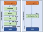
Figure 1: VSORA architecture replaces the traditional multi-level memory hierarchy with a unified, massive flat register file to minimize data movement latency.
VSORA replaces this uncertainty with a large, explicitly managed memory structure. The MPU includes a massive, software-visible register file implemented as several megabytes of tightly coupled memory, or TCM. This memory sits physically close to the compute engines and behaves like a flat, deterministic scratchpad rather than a cache. Its capacity is sufficient to hold entire weight matrices and intermediate activations on-chip, allowing the system to operate without relying on speculative caching behavior. See figure 1.
By designing around tensor-level locality and provisioning enough on-chip storage to support it, the MPU ensures consistent access latency. As long as the working set fits within the TCM, memory access times remain uniform and predictable. This eliminates the performance cliffs that often occur when cache hierarchies are overwhelmed, a common issue in large neural networks.
Continuous Pipelining and Deterministic Throughput
Once data is resident in the TCM, the MPU leverages highly efficient prefetching techniques to minimize latency. Instead of treating AI workloads as a series of discrete kernel launches, VSORA views them as sustained computational flows. An intuitive way to think about this is as an assembly line: once the pipeline is filled, new results emerge at a steady rate every cycle.
This pipelining operates at multiple levels. At the micro-architectural level, data streams continuously into compute units without stalls. At the instruction level, preparation and execution overlap so that hardware resources remain fully utilized. The architecture also allows multiple MPUs to be chained together, enabling data to flow directly from one unit to the next without detouring through external memory. After an initial warm-up period, throughput stabilizes and becomes largely independent of the complexity of individual operations.
Automated Data Layout and Reduced Software Burden
Another area where the MPU reduces developer burden is data layout. On many accelerators, achieving high performance requires manually rearranging data in memory to match hardware-specific access patterns. This process is error-prone, time-consuming, and often ties software to a specific architecture.
VSORA intentionally removes this responsibility from the programmer by introducing a memory access abstraction. The MPU hardware automatically handles alignment, padding, swizzling, and internal data reordering needed to sustain peak bandwidth. Developers work with tensors as abstract mathematical objects, while the hardware transparently performs the low-level transformations required for efficient execution. This approach not only improves productivity but also reduces performance fragility caused by subtle layout mismatches.
These architectural choices make the VSORA MPU particularly well suited for inference workloads, where latency and predictability matter more than raw peak throughput. Unlike GPUs, which often require large batch sizes to amortize overheads and reach high utilization, the MPU remains efficient even with batch size one. This is critical for real-time applications such as robotics, autonomous systems, and interactive AI, where waiting to accumulate large batches is not an option.
Dataflow Execution Model
In conventional multi-core and multi-accelerator systems, scaling often introduces diminishing returns due to synchronization overhead and shared memory contention. Additional compute resources increase coordination costs, reducing effective throughput.
Instead of treating each processing unit as an independent island, multiple MPUs are connected into a single, deeply pipelined dataflow graph. The output of one MPU becomes the direct input of the next, enabling true zero-copy execution at the hardware level.
Each MPU maintains its own TCM, allowing large models to be partitioned cleanly across units. Data moves directly between register files rather than through external memory interfaces, which is especially advantageous for the hot data paths common in modern neural networks. As models scale, throughput remains flat and predictable as long as active tensors fit within the available TCM.
Simplified Scaling and System-Level Efficiency
From a system-level perspective, this results in an architecture that scales without imposing additional complexity on developers. Instead of implementing intricate tiling strategies, synchronization mechanisms, and scheduling logic, programmers define tensor flows and dependencies. The hardware autonomously manages execution, handshaking, and scheduling, ensuring consistent performance even under tight latency constraints.
This makes the VSORA architecture especially conducive to high-pressure environments such as cloud inference platforms, edge deployments, and autonomous systems, where strict latency budgets leave no room for scheduling inefficiencies or unpredictable stalls.
Conclusion
By eliminating kernel launch overhead and dismantling the traditional memory wall between layers, the VSORA Matrix Processing Unit redefines AI efficiency at its core. It delivers near-peak hardware utilization even at batch size one—something conventional accelerators simply cannot achieve. Performance is no longer dependent on artificial batching to mask architectural inefficiencies.
This makes the architecture uniquely suited for interactive and real-time AI, where milliseconds determine safety, usability, and user experience. From real-time autonomy to fluid conversational systems, VSORA prioritizes determinism, latency consistency, efficiency, architectural simplicity, and cost effectiveness over brute-force parallelism.
Equally transformative is the ease of adoption. There is no new programming model, no proprietary language, no disruptive toolchain shift. Developers continue using familiar frameworks such as TensorFlow, PyTorch, or ONNX—without rewriting models or retraining teams. Transitioning to VSORA requires no paradigm change, only performance gains.
In short, the VSORA MPU does not just accelerate AI workloads—it removes the structural bottlenecks that have defined them.
In a significant advancement for the semiconductor industry, Caspia Technologies announced the broad availability of CODAx V2026.1, its flagship RTL security analyzer. The new release strengthens early-stage hardware security verification and positions the company to deliver fully agentic workflows that automate vulnerability detection, triage, and remediation across the entire chip design lifecycle.
CODAx functions as a security-aware static auditing solution specifically engineered for early RTL code in IP and SoC designs. It scans for over 150 insecure coding practices that can introduce vulnerabilities, offering immediate, actionable correction suggestions to designers. What sets CODAx apart is its foundation in public vulnerability databases including CWE, CVE, and Trust-Hub, which collectively document more than 1,000 known hardware security weaknesses. Caspia employs generative AI techniques to systematically map these weaknesses to detectable RTL coding patterns, enabling proactive identification without requiring deep security expertise from every design engineer.
The V2026.1 release introduces deeper, hierarchy-spanning security checks that detect weaknesses propagating up and across design modules—a critical capability for complex modern SoCs. Caspia validated the update through rigorous stress testing on more than 10,000 intentionally vulnerable designs, confirming its robustness and accuracy. In a real-world demonstration, CODAx analyzed a popular open-source root-of-trust design comprising over 400 design files, approximately 3 million gates, and 500,000 lines of RTL code. The entire process took roughly 45 minutes and uncovered multiple previously undetected security weaknesses.
Industry adoption has been swift. Major chip and system companies worldwide are deploying CODAx across diverse applications, including automotive, data center, communications, storage, multimedia, precision analog, and embedded computing. Caspia has collaborated closely with leading EDA suppliers to ensure seamless integration into existing design flows, minimizing disruption while maximizing security gains. The tool’s CI/CD compatibility further supports continuous security checking, delivering what the company describes as 10x efficiency improvements, reducing vulnerability discovery and remediation from days or weeks to minutes.
To accelerate its vision of agentic security platforms, Caspia has strengthened its leadership team with the appointment of Stuart Audley as Vice President and General Manager of Product Management. Audley brings decades of specialized experience in cryptographic hardware and security IP development for top defense contractors and premier semiconductor firms. He previously led advanced security platform initiatives for FPGAs and ASICs at The Athena Group, Inc. and Mercury Systems.
“We are expanding our security verification footprint to include both advanced tools and enablement of agentic workflows,” said Rick Hegberg, CEO of Caspia Technologies. “I am delighted to add someone with Stuart’s experience and background to the team. This will ensure we can focus on delivering cutting-edge capabilities and AI-driven security automation.”
Audley echoed the strategic shift: “Caspia is evolving from a provider of point security verification tools to an agentic platform supplier where AI orchestrates comprehensive hardware security workflows. The elements of our plan include unifying all our tools with AI-assisted workflows that span the entire hardware security lifecycle: analyzing RTL, identifying vulnerabilities, and verifying the results. Traditional design flows remain fully supported, but we are creating a new category for agentic-enabled hardware security verification.”
Caspia will showcase its latest technology, including CODAx V2026.1 and previews of its agentic roadmap, at DVCon 2026 in booth 702. The event runs March 2-5 at the Santa Clara Hyatt Regency in Santa Clara, California. Attendees can register at the official DVCon website.
Founded in 2020 and headquartered in Gainesville, Florida, Caspia Technologies is a privately held innovator in AI-enabled chip and system security. The company blends advanced tools and intelligent agents with existing design flows to deliver expert-level security capabilities to all engineering teams. Drawing on deep expertise in chip design, fabrication, test, verification, and hardware security threats, Caspia aims to secure the future of silicon through proactive, scalable solutions.
With the semiconductor industry facing escalating hardware security challenges—from side-channel attacks to supply-chain vulnerabilities—CODAx represents a timely and powerful response. By empowering designers to address issues at the earliest RTL stage, Caspia is not only reducing risk but fundamentally transforming how secure chips are developed. As the company transitions toward a full agentic platform, the industry can expect even greater automation and assurance in the years ahead.
At the 2026 Chiplet Summit, Synopsys presented a bold vision for the future of semiconductor innovation: AI-driven multi-die design powered by agentic intelligence. As the semiconductor industry shifts rapidly toward chiplet-based architectures and 3D stacking, the complexity of design, verification, and system integration has increased dramatically. Traditional methodologies, while powerful, are no longer sufficient to keep pace with market demands for higher performance, lower power, faster time to market, and greater reliability. AI is now emerging as the transformative catalyst that re-engineers the entire multi-die design workflow.
Industry momentum behind chiplets and advanced packaging technologies is accelerating. A significant percentage of design teams are already implementing or planning multi-die architectures in their next-generation products. The global semiconductor packaging market is projected to grow substantially through 2033, fueled by 3D stacking, 2.5D interposers, embedded silicon bridges, and fan-out wafer-level packaging. This growth reflects a fundamental shift: system-level performance gains are increasingly achieved through heterogeneous integration rather than traditional monolithic scaling.
At the same time, artificial intelligence models themselves are driving unprecedented hardware requirements. The evolution from early neural networks like AlexNet to transformer-based architectures such as BERT and large-scale systems like GPT-4 demonstrates exponential growth in parameter counts and computational demand. These AI workloads require advanced multi-die systems capable of delivering massive bandwidth, low latency, and optimized power efficiency. Hardware innovation is therefore both driven by AI and enabled by AI, a powerful feedback loop shaping the next decade of semiconductor design.
However, multi-die design introduces immense multidimensional complexity. Engineers must simultaneously optimize system partitioning, die-to-die connectivity, packaging, power delivery, thermal behavior, signal integrity, verification coverage, and software modeling. Achieving optimal results traditionally requires repeated cycles of tuning tool options, analyzing outputs, and rerunning flows, an iterative search across a vast solution space. Expert engineers rely on years of experience to navigate these trade-offs efficiently.
AI transforms this process by enabling engineering teams to perform like experts at scale. Machine learning models correlate tool settings with performance outcomes, learn the impact of design choices, and guide optimization decisions intelligently. For example, AI-driven die-to-die routing techniques have demonstrated dramatic improvements in runtime and signal integrity. Frequency-domain metrics can accelerate optimization, while time-domain eye-diagram analysis provides higher fidelity insights. By combining these intelligently, AI achieves faster convergence with improved quality of results.
Verification also benefits significantly from AI assistance. Traditional constrained-random approaches often require thousands of test seeds to reach target coverage. AI-assisted verification expands coverage while reducing the number of required tests, achieving faster time-to-results and improved quality-of-results (QoR). This reduction in redundant test iterations directly shortens development cycles and lowers compute costs.
Beyond digital implementation and verification, AI is reimagining multiphysics analysis. Machine learning-enabled solvers accelerate simulation across electrical, thermal, and mechanical domains. Reduced-order models and digital twins enable rapid lifecycle exploration, while generative AI systems assist with scripting, constraint generation, and workflow optimization. These capabilities create predictive, fast, and high-fidelity design environments that were previously unattainable.
One of the most compelling advancements presented is the concept of agentic AI, AI systems that go beyond assistance to autonomous orchestration. Instead of merely suggesting optimizations, agentic AI can plan, act, and make decisions within defined objectives. This evolution moves from simple task execution (L1 assistance) toward full workflow autonomy (L5 decision-making). Engineers increasingly collaborate with AI “co-workers” capable of autonomously partitioning multi-die systems, optimizing power networks, resolving signal integrity violations, and even improving RTL for power and performance.
Industry leaders recognize this shift. My favorite semiconductor CEO Jensen Huang of Nvidia has publicly stated that AI employees will become commonplace, envisioning a future where organizations deploy large numbers of AI-driven engineering agents. This perspective underscores the growing confidence that autonomous AI systems will fundamentally augment, and in some cases transform engineering workflows.
The productivity gains reported by leading CPU, GPU, memory, and hyperscale infrastructure providers reinforce this momentum. Tasks that previously required days can now be completed in hours, or even minutes, through AI assistance. Such improvements are not incremental; they represent a structural change in how semiconductor innovation progresses.
Bottom line: AI-driven multi-die design is not merely about automation, it is about amplification. By combining human expertise with autonomous AI agents, the industry can break through existing performance barriers, reduce time to market, and manage escalating system complexity. As advanced packaging technologies continue to grow and AI workloads expand, agentic AI will become indispensable in shaping the future of semiconductor engineering.
In a break from our academic-centric picks, here we look at an agentic verification flow developed within a semiconductor company. Paul Cunningham (GM, Verification at Cadence), Raúl Camposano (Silicon Catalyst, entrepreneur, former Synopsys CTO and lecturer at Stanford, EE292A) and I continue our series on research ideas. As always, feedback welcome.
Nice paper on using agentic methods for hands-free formal verification. The goal is to explore how much can be achieved with a semi/fully autonomous agentic formal flow: understand design specifications, create a verification plan, allocate tasks to several AI verification engineers, communicate with formal verification to prove properties. Then analyze counter examples, assess formal coverage, and improve by adding missing properties.
Credible effort.
Paul’s view
This paper from Infineon outlines a simple agentic workflow for formally verifying RTL. Commercial verification agents have evolved quite a bit since it was published a year ago, but it still makes for a nice read. The paper begins by walking the reader through prompt engineering concepts like feedback, refinement, chain-of-thought, as well as sampling-and-voting as a method to mitigate hallucinations. The authors make their workflow available on three different open-source frameworks – CrewAI, AutoGen, and LangGraph. The workflow creates a list of properties to prove in plain English (verification plan), then creates and refines System Verilog Assertions (SVAs) for each property, and then runs a commercial model checking tool (Jasper from Cadence) on those SVAs. Each step in the workflow is iterative with multi-shot LLM calls.
The authors benchmark their agent on a range of simple testcases, typically with around 10 properties generated per testcases. All the testcases are considered golden RTL (bug free). The authors benchmark code coverage for the properties generated and how many of these pass in formal. Even though the circuits are fairly simple, both proof rates and coverage average below 50%. Also, in real world situations the RTL is not known to be golden and one of the biggest challenges for agentic workflows is to determine if a proof failure is due to a bad property or a real bug in the design. That said, one year is a long time in AI, and where last year was a breakthrough year for agentic software coding, our view at Cadence is that this year looks set to be a breakthrough year for agentic RTL design and verification. I’m looking forward to several exciting new papers on the topic at upcoming conferences!
Raúl’s view
Launched in early 2024 by Cognition AI, Devin is an autonomous AI agent designed to handle end-to-end software development tasks. Devin created a strong initial buzz, after the dust settled it reportedly resolved about 14% of real-world GitHub issues on the SWE-bench unassisted (vastly outperforming previous AI models). This month’s blog is about Saarthi, “a similar fully autonomous AI formal verification engineer”. Saarthi uses multi-agent collaboration and tight integration with formal tools, enabling systematic property generation, proof and coverage analysis aligned with industrial verification practice.
Saarthi leverages recent work in multi-agent LLM frameworks, applying workflows such as planning, reflection, tool use, and human-in-the-loop to formal hardware verification. It integrates LLMs, a framework (in today’s LLM literature “the control, coordination, and tooling layer around one or more LLMs”) and a tool (an external capability, formal verification) to build “the first AI formal verification engineer”. Human-in-the-loop intervention remains essential to avoid infinite loops and resolve ambiguous or incorrect properties.
Saarthi is evaluated across a broad spectrum of RTL designs ranging from simple counters and FSMs to more complex structures such as FIFOs, pipelined adders, and an RV32I core, using three different LLMs. The good news is that end-to-end autonomous formal verification is achievable in a meaningful fraction of cases, success rates hover around 40–50%. Coverage metrics are consistently stronger than assertion proof rates, not surprising as the first few assertions tend to cover a disproportionately large fraction of the reachable state space and the number of properties is small (10-20). Model choice matters significantly: GPT-4o emerges as the most robust and consistent, Llama3-70B underperforms across nearly all metrics. Agentic workflows can mitigate, but not eliminate, underlying model weaknesses. The results support “AI-assisted verification under human supervision” more than “hands-off AI verification”. From a practical perspective, this is still valuable; Saarthi is a credible systems-level demonstration of agentic AI applied to formal verification.
While they don’t fully achieve a completely autonomous engineering system, the authors convincingly demonstrate that modern LLMs in a carefully designed agentic workflow and human-in-the-loop control, can handle substantial parts of an industrial formal verification flow. At the same time, the results make clear that today’s LLMs remain probabilistic assistants rather than deterministic engines — success rates vary, retries are frequent, and human intervention remains necessary for successful outcomes. The paper is an important datapoint in the progress of AI-assisted EDA. As for the bold claim that “Artificial General Intelligence (AGI) by 2027 is strikingly plausible, and we believe that Saarthi could be pivotal in reaching that milestone within the hardware design verification domain”, only time will tell.
At the 2025 RISC-V Summit, amid debates over cloud scaling and AI cost, DeepComputing CEO Yuning Liang offered a radical view: the future of intelligence isn’t in the cloud at all — it’s already in your pocket. His lunchtime conversation began with iPhones and ended with the death of the operating system. In between, he sketched a vision of computing that dissolves centralized infrastructure into personal devices, reshaping everything from hardware to human interaction.
Why Do You Need the Cloud?
Yuning waves his phone and laughs. “People keep saying, ‘We need the cloud for AI.’ Why? You’ve already got the compute right here. The only thing missing is space to store your models.” The cloud is no longer the default; it’s just a backup. In Yuning’s framing, bigger storage tiers aren’t luxury upgrades — they’re AI capacity ratings.
He taps on his iPhone’s storage line: “See? 64 gigabytes isn’t just storage — it’s intelligence. You want Whisper for voice, a 7B LLM for reasoning, a vision model for your camera? Fine. They all live here.” Thanks to aggressive model quantization — including FP4 and FP8 formats — today’s smartphones can host multiple intelligent agents. Storage becomes the limit on your on-device intelligence.
William Gibson imagined this in 1988. In Mona Lisa Overdrive, Kumiko carried a pocket-sized Maas-Neotek biochip that projected an AI companion named Colin — visible only to her, contextually aware, able to access local systems and provide guidance. Thirty-seven years later, Yuning is describing essentially the same device. Gibson conjured it decades before we had the silicon to build it.
Today, Yuning argues, correctness is perceptual, not mathematical. If your LLM gets one token wrong out of a million, no one notices. He shakes his head. “In the 20th century, if Intel was off by 0.001 in floating point, it was a crisis. Divide-by-zero? Immediate trap, big exception. That was engineering pride.”
“In RISC-V, you don’t even need to take the divide-by-zero exception,” he says. “Just flag it. Keep running. Why waste cycles pretending to be perfect when the output is statistical anyway?” This mindset shift explains the rise of ultra-low-precision formats like FP4. What matters isn’t IEEE-754 perfection — it’s the human experience.
“The user interface is a relic,” Yuning says. “You won’t open apps in ten years. You’ll forget what a mouse was. You’ll just tell your glasses what you want.” He describes a lightweight AI OS — not an operating system in the old sense, but a runtime that manages models, sensors, and context. One orchestrator that knows who you are, what you’re doing, and loads the right model at the right moment. No menus. No icons. Just interaction.
When the topic turns to silicon, Yuning grows animated. “Everyone’s building SoCs like they’re building cities — giant, expensive, unmanageable,” he says. “I just want to build the brain.” To Yuning, the ideal AI processor is scalar, vector, and matrix compute wrapped around fast SRAM — maybe GDDR6. Everything else (I/O, radios, sensors) is the body. Let the OEMs build the hands and eyes. His job is to supply the cortex.
“The chiplet model fits perfectly,” he says. “Each part is an organ. You snap them together.” This modular vision aligns with the Open Chiplet Architecture, which promotes interoperable compute, memory, and I/O units. Yuning never names OCA directly, but the alignment is unmistakable. “Just make sure the interfaces fit.”
“Everyone’s obsessed with 1024-bit vectors and out-of-order cores,” Yuning says, voice rising an octave. “They’re expensive, they’re hot, and they don’t scale. Why do that?”
Instead, he champions deterministic simplicity. “If you can get the same user-perceived performance with half the power and half the cost, you win. Don’t chase benchmark vanity. Build something that feels fast.”
Here, he echoes a rising sentiment within the RISC-V community — seen in startups like Simplex Micro — that favors deterministic scheduling over speculative execution. Elegance, Yuning suggests, is the new performance metric.
How can a startup survive against Nvidia and Apple? “Do everything with ten times less — people, money, time,” he says. “That’s the rule.” Big companies, he argues, have thousands of engineers managing thousands more. Startups survive by constraint and speed. “We can do in a week what they do in a quarter — if we stay hungry.”
And forget the cloud. “Cloud is not for startups,” Yuning says. “It’s complex and slow. Don’t envy Cerebras or Groq — unless you want to raise money and become another big corporate like OpenAI or Anthropic.” He laughs. “Once you have hundreds of people, thousands of people? You lose the speed. You get all the bad odds — wasting money, wasting time, wasting opportunities. Like government.”
The key isn’t to outspend giants. It’s to out-focus them.
Yuning’s closing prediction: “You’ll wear your computer,” he says. “Glasses, earbuds, maybe a pendant. They’ll talk to each other through local models. No screen, no keyboard. The model is the interface.” The core, he insists, will be a small deterministic brain — not a GPU farm.
The Evaporating Cloud
“Fast, private, local. That’s the future. The cloud becomes the teacher; your device becomes the student. Once it learns, the cloud becomes an artifact.” When that happens, Yuning says, computing will finally be personal again.