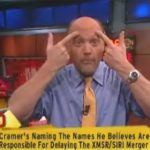
100X800 Banner (1)

Checking AMS design rules instantly

Checking AMS design rules instantly
by Paul McLellan on 03-13-2011 at 5:25 pm

With each process generation, the design rules get more and more complex. One datapoint: there are twice as many checks at 28nm as there are at 90nm. In fact, the complexity of the rules is outpacing the ability to describe them using the simplified approaches used in the DRCs built-into layout editors or formats like LEF.

Worse still, at 28nm and below the rules are really too complicated for a designer to understand. As Richard Rouse of MoSys said “at 28nm, even the metal rules are incomprehensible.” It goes without saying that the rules for the even more critical layers for transistor formation are even more opaque.

It is going to get worse too, since at 22nm and below we will need to use double patterning for the most critical layers, which means that it is not really even possible to know whether a design is in compliance, that depends on the double patterning algorithm being able to assign shapes to the two patterns in a way that the lithography will work.

It used to be that analog designers were comfortable staying a couple of nodes behind the digital guys but that is no longer possible. 70% of designs are mixed-signal SoCs, driven by the communications market in particular. Mobile consumer chips need analog, and even some of the digital, such as graphics accelerators, typically require custom design datapaths.

Digital designs are about scaling, using simplified rules to be able to handle enormous designs. Custom and analog design is about optimization and so need to push to the limits of what the process can deliver.

The only solution to this problem is to run the real signoff DRC with the real signoff rules. The signoff DRC is pretty much universally Mentor’s Calibre (sorry Cadence and Synopsys). But running Calibre from within theLaker™ Custom Layout Automation System is inconveniently slow and disruptive. So Mentor have created an integratable version called Calibre RealTime (and by the way, doesn’t Mentor know that Oasys have a product already called RealTime Designer) which operates on top of the OpenAccess (OA) database and Laker is the first, and so far only, layout editor to do the integration. Rules are continuously checked in parallel with editing. A full check takes about 0.2 to 0.3 seconds. In the demonstration I saw at Springsoft’s booth it was almost instantaneous, rather like the spell-checker in a word processor. In fact at 28nm it was checking 6649 shapes in 0.3 second. Laker optimizes which checks are required based on what changes were made to the design (if you don’t change the metal you don’t need to run those metal checks again, for example) which further improves performance.

Historically, layout designers have been very reluctant to adopt anything that might slow them down. But the complexity of the rules in modern process nodes along with the high performance and unobtrusiveness of the integration, has a good chance of immediate adoption of the Laker signoff-driven layout flow.


Moore’s Law and Semiconductor Design and Manufacturing

Moore’s Law and Semiconductor Design and Manufacturing
by Daniel Nenni on 03-12-2011 at 4:51 am

The semiconductor design and manufacturing challenges at 40nm and 28nm are a direct result ofMoore’s Law, the climbing transistor count and shrinking geometries. It’s a process AND design issue and the interaction is at the transistor level. Transistors may be shrinking, but atoms aren’t. So now it actually matters when even a few atoms are out of place. So process variations, whether they are statistical, proximity, or otherwise, have got to be thoughtfully accounted for, if we are to achieve low-power, high-performance, and high yield design goals.

"The primary problem today, as we take 40 nm into production, is variability,” he says. “There is only so much the process engineers can do to reduce process-based variations in critical quantities. We can characterize the variations, and, in fact, we have very good models today. But they are time-consuming models to use. So, most of our customers still don’t use statistical-design techniques. That means, unavoidably, that we must leave some performance on the table.”Dr. Jack Sun, TSMC Vice President of R&D

Transistor level design which lnclude Mixed Signal, Analog/RF, Embedded Memory, Standard Cell, and I/O, are the most susceptible to parametric yield issues caused by process variation.

Process variation may occur for many reasons during manufacturing, such as minor changes in humidity or tempature changes in the clean-room when wafers are transported, or due to non uniformities introduced during process steps resulting in variation in gate oxide, doping, and lithography; bottom line it changes the performance of the transistors.

The most commonly used technique for estimating the effects of process variation is to run SPICE simulations using digital process corners provided by the foundry as part of the spice models in the process design kit (PDK). This concept is universally familiar to transistor level designers, and digital corners are generally run for most analog designs as part of the design process.

Digital process corners are provided by the foundry and are typically determined by Idsat characterization data for N and P channel transistors. Plus and minus three sigma points maybe selected to represent Fast and Slow corners for these devices. These corners are provided to represent process variation that the designer must account for in their designs. This variation can cause significant changes in the duty cycle and slew rate of digital signals, and can sometimes result in catastrophic failure of the entire system.
However, digital corners have three important characteristics that limit their use as accurate indicators of variation bounds especially for analog designs:

  • Digital corners account for global variation, are developed for a digital design context and are represented as “slow” and “fast” which is irrelevant in analog design.
  • Digital corners do not include local variation effects which is critical in analog design.
  • Digital corners are not design-specific which is necessary to determine the impact of variation on varying analog circuit and topology types.

These characteristics limit the accuracy of the digital corners, and analog designers are left with considerable guesswork or heuristics as to the true effects of variation on their designs. The industry standard workaround for this limitation has been to include ample design margins (over-design) to compensate for the unknown effects of process variation. However, this comes at a cost of larger than necessary design area, as well as higher than necessary power consumption, which increases manufacturing costs and makes products less competitive. The other option is to guess at how much to tighten design margins, which can put design yield at risk (under-design). In some cases under and over-design can co-exist for different output parameters for a circuit as shown below. The figure shows simulation results for digital corners as well as Monte Carlo simulations which are representative of the actual variation distribution.

To estimate device mismatch effects and other local process variation effects, the designer may apply a suite of ad-hoc design methods which typically only very broadly estimate whether mismatch is likely to be a problem or not. These methods often require modification of the schematic and are imprecise estimators. For example, a designer may add a voltage source for one device in a current mirror to simulate the effects of a voltage offset.

The most reliable and commonly used method for measuring the effects of process variation is Monte Carlo analysis, which simulates a set of random statistical samples based on statistical process models. Since SPICE simulations take time to run (seconds to hours) and the number of design variables is typically high (1000s or more), it is commonly the case that the sample size is too small to make reliable statistical conclusions about design yield. Rather, Monte Carlo analysis is used as a statistical test to suggest that it is likely that the design will not result in catastrophic yield loss. Monte Carlo analysis typically takes hours to days to run, which prohibits its use in a fast, iterative statistical design flow, where the designer tunes the design, then verifies with Monte Carlo analysis, and repeats. For this reason, it is common practice to over-margin in anticipation of local process variation effects rather than to carefully tune the design to consider the actual process variation effects. Monte Carlo is therefore best suited as a rough verification tool that is typically run once at the end of the design cycle.

The solution is a fast, iterative AMS Reference Flow that captures all relevant variation effects into a design-specific corner based flow which represents process variation (global and local) as well as environmental variation (temperature and voltage).

Graphical data provided by Solido Design Automation‘s Variation Designer.


Getting Real Time Calibre DRC Results

Getting Real Time Calibre DRC Results
by Daniel Payne on 03-10-2011 at 10:00 am

Last week I met with Joseph Davis, Ph.D. at Mentor Graphics in Wilsonville, Oregon to learn about a new product designed for full-custom IC layout designers to improve productivity.

The traditional flow for full-custom IC layout designers has been nearly unchanged for decades:

  • Read a schematic or use Schematic Driven Layout (SDL)
  • Create an IC layout with polygons, objects, generators or cells
  • Manually interconnect or use a P&R tool
  • Run DRC and LVS in batch
  • Find and fix errors

As designers use the newest layout nodes at 28nm the complexity explosion in DRC rules has been quite daunting with a doubling of rules compared to 90nm:

IC layout designers cannot keep all of these new rules in their head while doing custom layout and running DRC tools in batch mode dozens or hundreds of times a day will certainly slow down design productivity.

Faced with these pressures of more DRC rules and increased difficulty to get a clean layout a design team could choose several options:

[LIST=1]

  • Avoid optimizing the layout, just get it to DRC, LVS clean and get the job done.
  • Take more time to get the layout clean.
  • Hire more layout designers or contractors.

    None of these options looks appealing to me, so it was good news to hear about a new approach to make the life of IC layout design go faster. This approach is to use the Calibre tool interactively while doing IC layout instead of using it in batch mode:

    The demo that I saw was a custom IC layout at 28nm with dozens of transistors, 6,649 shapes and about 3,000 checks. When this layout was run with Calibre in batch mode it took about 20 seconds to produce results, however when used interactively the results came back in under 1 second. Both runs used identical rule decks for Calibre, and were run on the same CPU, the difference being that the interactive version of Calibre produced near instant results.

    Mentor calls this new tool Calibre RealTime and it works in a flow that uses the Open Access database, a de-facto industry standard. It was a bit odd to be inside of a Mentor building and watch a demo using the SpringSoft Laker tool for IC layout since it competes with IC Station from Mentor. You can get this same technology for Mentor’s IC Station tool but you have to wait until July.

    Benefits of this interactive approach with Calibre RealTime are:

    • I can see my DRC errors rapidly, just mouse over the error region and read a detailed description of my DRC violations.

    • The DRC rule deck is the full Calibre deck, so I’m getting sign-off quality results at the earliest possible time. In the past IC tools had some rudimentary interactive DRC checks however they were never sign-off quality, so you still had to run a batch DRC run only to discover that you had lot of fixes still required.
    • With the SpringSoft Laker tool I just push one button and get Calibre results in under a second. There’s no real learning curve, it’s just that simple to install and start using immediately.
    • Of course I wouldn’t run this interactive DRC check on a design with more than 1,000 transistors at a time, it’s really meant for smaller blocks. If you use Calibre RealTime while your design is being created on small blocks, then it’s going to catch your DRC errors almost instantly so you can start fixing the layout and avoiding making the same mistake again.
    • Mentor IC Station users will benefit from this same productivity boost in just a few months, so you should be able to see a demo at DAC.
    • Works with MCells, PCells, routers andmanual editing. So it fits into your IC flow at every step of the process.

    Summary
    The Calibre RealTime tool will certainly save you time on full-custom IC layout by producing DRC results in under a second on small blocks. SpringSoft Laker users will benefit first, then IC Station users in a few months.

    It makes sense for Mentor tools to work with the Open Access database, now I wonder if IC Station will be the next tool to use OA?


  • Semiconductor IP would be nothing without VIP…

    Semiconductor IP would be nothing without VIP…
    by Eric Esteve on 03-10-2011 at 6:35 am

    …but what is the weight of the Verification IP market?

    If the IP market is a niche market (see: **) with revenue of about 1% of the overall semiconductor business, how could we qualify the VIP market? Ultra-niche market? But the verification of the IP integrated into the SoC is an essential piece of the engineering puzzle when you are involved in SoC design. Let me clarify what type of verification I want to discuss: the verification of a protocol based function, which can be an Interface protocol (USB, PCIe, SATA, MIPI and more), a specific memory Interface (DDR, DDR2,…, GDDR,…, Flash ONFI and more) or a Bus protocol (AMBA AXI,…, OCP and more).

    ** http://www.semiwiki.com/forum/f152/ip-paradox-such-low-payback-such-useful-piece-design-369.html

    Courtesy of Perfectus
    The principle of this type of VIP is: you write Test benches, send to a scenario Generator which activates the Drivers of the Bus Function Model (BFM), accessing the function you want to verify, the Device Under Test (DUT). The Verification Engine itself is made of the transaction Generator, Error injector and so on and of the BFM, which is specific to the protocol and to the agent configuration: if the DUT is a PCIe Root Port x4, the BFM will be a PCIe End Point x4. If the DUT is the hand, the BFM is the glove. When you write Test benches, you in fact access to a library of protocol specific test suite (test vectors written by the VIP vendor), which is sold on top of the VIP. So, after applying test benches, you have now to monitor the behavior of the DUT and check for the compliance with the protocol specification. This defines another product sold by the VIP vendor: the Monitor/Checker, which allows you to evaluate both the coverage of your Test Benches, and the compliance in respect with the protocol.

    Common sense remark about the BFM and IP: when you select a VIP provider to verify an external IP, it is better to make sure that the design team for the BFM and for the IP are different and independent (high level specification and architecture made by two different person). This is to avoid the “common mode failure”, principle well known in aeronautic for example.

    If we look at this products from a cost perspective, the unit cost is relatively low (in the few $10K), but as you probably know, the verification task weight is heavy (60 or 70% of the overall design project), so you want to parallelize as much as possible to minimize the time devoted to verification. To do so, you have to buy several licenses for the same VIP, ending up to a cost being in the few $100K per project. Now, if we try to evaluate the market size of the VIP, like we can do for the Design IP, we realize that there is no market data available. We simply don’t know it! Making an evaluation is absolutely not straightforward. You could think that looking at the number of IP licenses sold for protocol based function (above listed) could lead to a simple equation: Market Size = (Nb of IP Licenses) x (average cost of VIP).

    But that does not work! In fact, the people buying an IP do not necessarily run the complete Verification on it, but some IDM or Fabless do it: it is not a binary behavior! That you can say is that a design team who internally develop a protocol based function will most certainly run a complete Verification of the function. But you don’t know precisely how many IDM or Fabless prefer developing internally a protocol based function rather than buying an IP!

    If we look at the VIP players, we see that Cadence has heavily invested into this market: when they bought Denali in 2010 (for $315M), they bought a strong VIP port folio and competencies, and probably good market share. They also bought products from Yogitech SpA, IntelliProp Inc. and HDL Design House in October 2008 to complete their port-folio. When you consider that Synopsys integrates their VIP into Design Ware, so they do not try to get value for each VIP, you can say that there is a kind of Yalta: Design IP to Synopsys, VIP to Cadence. But Cadence is not alone, and face pretty dynamic competition, mostly coming from mid size companies with R&D based in India and sales offices in the US (VIP is design resources intensive), like nSys, Perfectus, Avery, Sibridge Technologies and more.

    The VIP paradox: we don’t know the market size, but VIP is an essential piece of the puzzle for SoC design, as most of the SoC are using several protocols based functions (sometimes up to several dozen). We don’t know if just selling VIP is a profitable business, or if you need to also provide design services (like many vendors do). That we propose is to run a market survey, asking to the VIP vendors to disclose their revenue, so we could build a more precise picture of this market, evaluating the current size, understand the market trends and building a forecast. The ball is in the VIP vendor camp!


    Apple Creates Semiconductor Opportunities . . .

    Apple Creates Semiconductor Opportunities . . .
    by Steve Moran on 03-09-2011 at 7:22 pm

    There has been a lot of press this past week surrounding the release of iPad2. While it has some significant improvements, they are, for the most part, incremental. In my view the lack of flash, a USB port and a memory card slot continue to be huge deficits. Until this past week my reservations about the iPad have been mostly theoretical, never having actually used one. Then, earlier this week I got a chance to use an iPad for half a day while traveling. It was an OK experience and, in a pinch, it would serve my needs, but I found myself wanting to get back to my laptop as soon as possible. I would even have preferred my little Dell netbook.

    I am already an Android user on my smart phone and I think that, when I make the leap to a pad, I will look for an Android platform.That said, I give Apple all the credit for creating a new challenge for its competitors, while continuing to lead the marketplace and creating the ultimate user experience, continuing to lead the pack and making buckets of money along the way.

    In the very near term it is certain there will be a plethora of Android (and other) pads. The iPad will continue to set the standard others will attempt to meet or exceed. With this background, I recently came across an article in the EEherald that addresses the substantial opportunities for semiconductor companies to be a part of the Android pad ecosystem. You can read the whole article here but these are the highlights:

    – In a very short period of time price will be nearly as as important as features.

    – With streaming media and real time communication, multicore processing (more than 2) will be essential.

    – The marketplace is likely to branch into application-specific pads such as health care, engineering, environmental. Much of the differentiation will be software, but hardware will play a role.

    – Power consumption will continue to be a major problem and opportunity.

    – There will likely be the need to include more radios.

    The EEherald article concludes by pointing out that the odds of any company getting their chips inside the Apple iPad are remote, but that with so many companies preparing to leap into the Android pad market this is a huge emerging market.

    I am looking forward to the burst of innovation that Apple has spawned.


    TSMC 2011 Technology Symposium Theme Explained

    TSMC 2011 Technology Symposium Theme Explained
    by Daniel Nenni on 03-09-2011 at 6:49 pm

    The 17[SUP]th[/SUP] Annual TSMC Technology Symposium will be held in San Jose California on April 5[SUP]th[/SUP], 2011. Dr. Morris Chang will again be the keynote speaker. The theme this year is “Trusted Technology and Capacity Provider”and I think it’s important to not only hear what people are saying but also understand why they are saying it, so that is what this blog is all about.

    You can bet TSMC spent a lot of time on this theme, crafting every word. When dealing with TSMC you have to factor in the Taiwanese culture which is quite humble and reserved. Add in the recent semiconductor industry developments that I have been tweeting and I offer you an Americanized translation for “Trusted Technology and Capacity Provider”, a phrase made famous by the legendary rock band Queen “We are the Champions!”

    DanielNenni #TSMC said to make 40nm Chipset for #INTEL’s Ivy Bridge CPU:
    http://tinyurl.com/46qk89b March 5

    DanielNenni #AMD contracts #TSMC to make another CPU Product:
    http://tinyurl.com/4lel5zy March 2

    DanielNenni #Apple moves #SAMSUNG designs to #TSMC:
    http://tinyurl.com/64ofq67 February 15

    DanielNenni #TSMC 2011 capacity 2 rise 20%
    http://tinyurl.com/4j5v6qtFebruary 15

    DanielNenni #SAMSUNG orders 1M #NVIDIA #TEGRA2 (#TSMC) chips:
    http://tinyurl.com/4aa2xo6February 15

    DanielNenni #TSMC and #NVIDIA ship one-billionth GPU:
    http://tinyurl.com/4juzdvd January 13

    TRUST in the semiconductor industry is something you earn by telling people what you are going to do then doing it. After inventing and leading the pure-lay foundry business for the past 21 years you have to give them this one: TSMC is the most trusted semiconductor foundry in the world today.

    TECHNOLOGY today is 40nm, 28nm, and 20nm geometries. Being first to a semiconductor process node is a technical challenge, but also a valuable learning experience, and there is no substitute for experience. TSMC is the semiconductor foundry technology leader.

    CAPACITY is manufacturing efficiency. Capacity is yield. Capacity is the ability to ship massive quantities of wafers. From MiniFab to MegaFab to GigaFab,TSMC is first in semiconductor foundry capacity.

    Now that you have read the blog let me tell you why I wrote it. The semiconductor foundry business is highly competitive which breeds innovation. Innovation is good, I like innovation, and would like to see more of it. Other foundries take note, the foundry business is all about TRUST, TECHNOLOGY, and CAPACITY.

    Right now I’m sitting across from Tom Quan, TSMC Design Methodology & Service Marketing, in the EVA Airways executive lounge. Both Tom and I are flying back from Taiwan to San Jose early to participate in tomorrow’s Design Technology Forum. Tom is giving a presentation on “Successful Mixed Signal Design on Advanced Nodes”. I will be moderating a panel on “Enabling True Collaboration Across the Ecosystem to Deliver Maximum Innovation”. I hope to see you there.


    Essential signal data and Siloti

    Essential signal data and Siloti
    by Paul McLellan on 03-05-2011 at 3:24 pm

    One of the challenges with verifying today’s large chips is deciding which signals to record during simulation so that you can work out the root cause when you detect something anomalous in the results. If you record too few signals, then you risk having to re-run the entire simulation when you omitted to record a signal that turns out to be important. If you record too many, or simply record all the signals to be on the safe side, then the simulation time can get prohibitively long. In either case, re-running the simulation or running it very slowly, the time taken for verification increases unacceptably.

    The solution to this paradox is to record the minimal essential set of data needed from the logic simulation to achieve full visibility. This guarantees that it will not be necessary to re-run the simulation without slowing down the simulation unnecessarily. A trivial example: it is obviously not necessary to record both a signal and its inverse since one value can easily be re-created from the other. Working out which signals form the essential set is not feasible to do by hand for anything except the smallest designs (where it doesn’t really matter since the overhead of recording everything is not high).

    SpringSoft’s Siloti automates this process, minimizing simulation overhead while ensuring that the necessary data is available for the Verdi system for debug and analysis.

    There are two basic parts to the Siloti process. Before simulation is a visibility analysis phase in which the essential signals are determined. These are the signals that will be recorded during the simulation. Then, after the simulation, is a data expansion phase when the signals that were not recorded are calculated. This is done on-demand, so that values are only determined if and when they are needed. Additionally, the signals recorded can be used to re-initialize a simulation and re-run any particular simulation window without requiring the whole simulation to be restarted from the beginning.

    Using this approach results in dump file sizes of around 25% of what results when recording all signals, and simulation turnround times around 20% of the original. With verification taking up to 80% of design effort these are big savings.

    More information:


    Mentor Graphics 1 : Carl Icahn 0!

    Mentor Graphics 1 : Carl Icahn 0!
    by Daniel Nenni on 03-04-2011 at 10:03 pm

    This is just another blog about Carl Icahn and his quest to conquer EDA, when in fact EDA is conquering him. It includes highlights from my dinner with Mentor Graphics and Physicist Brian Greene, the Mentor Q4 conference call, and meeting Mentor CEO Wally Rhines at DvCon 2011.

    It wasn’t just the free food this time, dinner with Brian Greene was big enough to lure me to downtown San Jose on a school night. Brian has his own Wikipedia page so you know he is a big deal. Mentor executives and their top customers would also be there and I really wanted to hear “open bar” discussions about the Carl Icahn saga. Unfortunately the Mentor executives did not show and nobody really knew what was going on with Carl, nor did they care (except for me), so the night was a bust in those regards.

    The dinner however was excellent and the “who’s who” of the semiconductor world did show up so it was well worth my time. Brian Greene’s lecture on parallel universes versus a finite universe was riveting. According to string theory there is nothing in modern day physics that precludes a “multiverse”, which totally supports the subplot of the Men in Black movie.

    The excuse used for the Mentor executives not coming to dinner was the Q4 conference call the next day. Turns out it was a very good excuse! No way could Wally sit through dinner with a straight face with these numbers in his pocket:

    Walden Rhines: Well,Mentor‘s Q4 ’11 and fiscal year set all-time records in almost every category. Bookings in the fourth quarter grew 45% and for the year, 30%. Revenue grew 30% in the fourth quarter and 14% for the year, the fastest growth rates of the big three EDA companies. Established customers continue to purchase moreMentor products than ever, with growth in the annualized run rate of our 10 largest contract renewals at 30%.

    The transcript for the call is HERE. It’s a good read so I won’t ruin it for you but it definitely rained on Carl Icahn’s $17 per share offer. Carl would be lucky to buy Mentor Graphics at $20 per share now! After careful thought, after thorough investigation, after numerous debates, I have come to the conclusion that Carl has no big exit here. If someone reading this sees a big exit for Carl please comment because I just don’t see it.

    Wally Rhines did make it to DvCon and he was all smiles, business as usual. His Keynote “From Volume to Velocity” was right on target! Wally did 73 slides in 53 minutes, here are my favorites:

    This is conservative compared to what I see with early access customers. Verification is a huge bottle neck during process ramping.

    The mobile semiconductor market is driving the new process nodes for sure. Expect that to continue for years to come.

    The SoC revolution is driving gate count. One chip does all and IP integration is key!

    Purchased IP will continue to grow so gentlemen start your IP companies!

    Sad but true.

    Here is the bottom line Mr Icahn: Verification and Test are not only the largest EDA growth applications, verification and test are very “sticky”. Mentor Graphics owns verification and test so Mentor Graphics is not going anywhere but up in the EDA rankings. If you want to buy Mentor Graphics you will have have to dig deep ($20+ per share).

    Related blogs:
    Personal Message to Carl Icahn RE: MENT
    Mentor Acquires Magma?
    Mentor – Cadence Merger and the Federal Trade Commission
    Mentor Graphics Should Be Acquired or Sold: Carl Icahn
    Mentor Graphics Should Be Acquired or Sold: Carl Icahn COUNTERPOINT


    Clock Domain Crossing, a potted history

    Clock Domain Crossing, a potted history
    by Paul McLellan on 03-03-2011 at 11:23 am

    Yesterday I talked to Shaker Sarwary, the senior product director for Atrenta’s clock-domain crossing (CDC) product SpyGlass-CDC. I asked him how it came about. The product was originally started nearly 8 years ago, around the time Atrenta itself got going. Shaker got involved about 5 years ago.

    Originally this was a small insignificant area of timing analysis. Back then there were few chips failing from CDC problems for two reasons. First, chips had few clock domains (many chips had only one so CDC problems were impossible) and second the chips were not that large. So CDC analysis was done by running static timing (typically PrimeTime of course) which would throw up the CDC paths as areas which are ignored by timing analysis. They could then be checked manually to make sure that they were correctly synchronized.

    But like so many areas of EDA, a few process generations later the numbers all moved. The number of clocks soared, the size of chips soared and more and more chips were failing due to CDC problems. To make things worse, CDC failures are typically intermittent, a glitch that gets through a synchronizer occasionally for example. But there were no tools to deal with this issue in any sort of automated way.

    Atrenta started by creating a tool that could extract the CDC paths and look for rudimentary synchronizers such as double flops (to guard against metastability). This structural analysis became more and more sophisticated, looking for FIFOs, handshakes and other approaches to synchronizing across clock domain boundaries.

    Eventually this purely structural approach alone was not enough and a functional approach needed to be added. This uses Atrenta’s static formal verification engine to check that various properties remain true under all circumstances. For example,consider the simple case of a data-bus crossing a clock domain along with a control signal; for this to be safe the data-bus signals must be stable when the control signal indicates the data is ready. Or, in the case of using a FIFO to create some slack between the two domains (so data can be repeatedly generated by the transmitter domain and stored until the receiver domain can accept it. The FIFO pointers need to be Gray coded (so that only one signal changes when the pointer is incremented or decremented, a normal counter generates all sorts of intermediate values when carries propagate) and again, proving this cannot be done simply by static analysis.

    When CDC errors escape into the wild it can be very hard to determine what is going on. One company in the US, for example, had a multki-million gate chip connecting via USB ports. It would work most of the time but freeze every couple of hours. It took 3 months of work to narrow it down to the serial interfaces. After a further long investigation it turned out that it was a CDC problem generating intermittent glitches. There were synchronizers but glitches must either be gated off (for data) or not generated (for control signals).

    Another even more subtle problem was a company in Europe that had an intermittent problem that, again, took months to analyze. It turned out that the RTL was safe (properly synchronized) but the synthesis tool modified the synchronizer replacing a mux (glitch-free) with a complex AOI gate (not glitch free).

    In a big chip, which may have millions of of CDC paths, the only approach is to automate the guarantees of correctness. If not you are doomed to spend months working out what is wrong instead of ramping your design to volume. More information on SpyGlass-CDC here.


    All you want to know about MIPI IP… don’t be shy, just ask IPnest

    All you want to know about MIPI IP… don’t be shy, just ask IPnest
    by Eric Esteve on 03-03-2011 at 10:14 am

    According with the MIPI Alliance, the year 2009 has been the time for MIPI specification to be developed, when 2010 was dedicated to Marketing and Communication effort to popularize MIPI technologies within the SC industry, finally the year 2011 is expected to see MIPI deployment in the mass market, at least in the Wireless (Handset) segment.
    MIPI is an Interconnect protocol offering several key advantages: strong modularity allowing minimizing power but also reaching high bandwidth when necessary (6 Gbps, 12 Gbps…), interoperability between IC coming from different sources: Camera Controllers (CMOS Image Sensor), Display Controller, RF Modem, Audio Codec and an Application Processor. It take advantage of the massive move from parallel to serial interconnect we have seen, illustrated by PCI Express replacing PCI, SATA replacing PATA etc… to use similar technologies in Mobile Devices, where low power is key, as well as the needs for higher and higher bandwidth.

    Even if MIPI as an IP market is still at the infant stage, we expect it to strongly grow in 2011, at least in the wireless handset segment. We have started to build a forecast for MIPI powered IC in production, for 2010-2015.

    The number of IC in production is a key factor to push for MIPI adoption as a technology: test issues have been solved, no impact on the yield and, last but not least, IC pricing going down, benefiting from the huge production quantities (almost 1Billion IC in 2010) generated by the wireless handset segment.This is true for the Application processor (OMAP5 and OMAP4 from TI, Tegra 2 from NVIDIA, U9500 from ST-Ericsson…) which can be reused for other Mobile Electronic Devices and also for the peripheral ASSP supporting Camera, Display, Audio Codec or Modem applications. These MIPI powered price optimized ASSP can be also used in segments like PC (Media Tablet) and for Mobile Devices in CE.

    The Tier 2 chip makers, playing in the wireless segment could minimize their investment in this new technology (need for an AMS design team) and gain TTM by externally sourcing MIPI IP if they want to enter into the lucrative high end segment (Smartphone), which grew by 71% in 2010. For the same reason, MIPI pervasion in the above mentioned new segments would then be eased by the availability of these ASSP and by off the shelf MIPI IP. Finally, the pervasion of MIPI should also occur in the mid range wireless handset (feature phones). The overall result for 2010-2015 IP sales forecast is shown here:


    Take a look at “MIPI IP survey” from IPnest
    See:http://www.ip-nest.com/index.php?page=MIPI
    it gives information about:
    MIPI powered IC Forecast 2010-2015

    IP Market Analysis: IP vendor competitive analysis, market trends
    MIPI IP 2010-2015 Forecast by Market segment:
    Wireless Handset
    Portable systems in Consumer Electronics
    PC Notebook & Netbook, Media Tablets
    License price on the open market for D-PHY & M-PHY IP, by technology node
    Penetration rate by segment for 2010-2015 of MIPI PHY and Controller IP?
    ASIC/ASSP world wide designs start, and related IP sales from 2010 to 2015?
    From Eric Esteve
    eric.esteve@ip-nest.com

    (**) MIPI is a bi-directional high speed serial differential signaling protocol, power consumption optimized and dedicated to the Mobile Devices, to be used to Interface chips within the system, at the board level. It uses a Controller (digital) and a mixed signal PHY. There are numerous specifications (DSI, CSI, DigRF, LLI…), but all of these rely on one of the two PHY specifications (D-PHY and M-PHY). M-PHY supports different modes of operation:

    • LP at frequency range of 10K-600Mb/s
    • HS at frequency range of 1.25 to 6 Gb/s

    The protocol is scalable, so you can implement one or more lanes in each direction.See:http://www.mipi.org/momentum