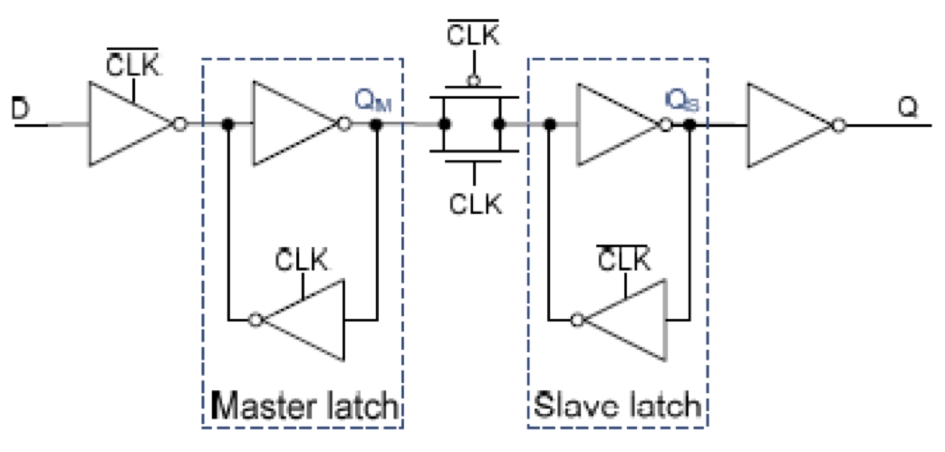
Recently, I discussed the increasing risk of metastability hazards at nanoscale geometries. These risks are significantly aggravated at low supply voltages and low temperatures and must be addressed during the design cycle of any mission critical application. This time I discuss what it takes to estimate a synchronizer’s mean-time between failures (MTBF).
Some flip-flops do a better job as a synchronizer than others. Sometimes you need to cascade flip-flops to get the MTBF your customer’s product needs. As the project manager, how are you going to decide about these issues when the engineer that designed the synchronizer flip-flop is not the engineer that integrates it into your final product?
 The engineer that designed your standard-cell synchronizer, call him Sam, should know about his circuit’s settling time constant and its metastability window. In fact, if the synchronizer is a master-slave (often the case), you need to know the settling time constant for the master and the slave, for a total of three parameters:

The engineer that integrates the synchronizer into a product, Ian, knows about the intended clock frequency, the average rate of input data transitions and the clock’s duty cycle.

To accurately estimate the synchronizer’s MTBF, all six of these parameters need to be known to you. Assuming you have them all, for an allowed settling time t, the formula is:

Clearly, the bigger (longer) the allowed selling time t, the better (longer) the MTBF. It’s also clear that t must be less than the clock period by, at least, the setup time of the next stage plus the delay of any logic between the synchronizer output and the next stage input.
The above formula for estimating MTBF is a familiar one except for the factor in the denominator of the exponent that represents the effective value of the settling time constant.

When the master and slave settling time constants are equal, then they both equal the effective settling time. This is true no matter the duty cycle. When the two settling time constants are not equal, the duty cycle can make a big difference in the settling time behavior. The duty cycle is usually around 0.5 and cannot vary too much without violating the clock minimum pulse-width constraint. However, for large differences in settling time constants, the duty cycle must be considered since it affects the exponent in the MTBF formula.
So both Sam and Ian each know three of the parameters that go into the MTBF estimate. Sam should specify his parameters at the worst-case corner: Typically SS, low-supply-voltage and low-temperature as specified by Ian for the product’s operational environment. Ian then specifies his parameters and calculates t and MTBF.
There are two novel issues that have appeared in this discussion. First, the effect of clock duty-cycle on MTBF has, until recently, been overlooked, but can be included by having the synchronizer’s standard-cell vendor specify the settling time constants of both the master and slave. Second, when it comes to synchronizers, standard-cell designers (Sam) and integrators (Ian) each have only half the MTBF story. They must work together to produce safe products for mission critical applications. The resulting products are neither over-designed nor unreliable. The Blendics metastability analysis tool, MetaACE, can help synchronizer vendors provide reliable parameter sets to their customers.
Increasingly, at nanoscale geometries, a single-stage synchronizer will not do the job that your customer wants and a multistage synchronizer is required. In Part 2 of this topic I will discuss the issues associated with estimating MTBF for these synchronizers (here is a hint: most published methods are not very good).
lang: en_US
Share this post via:


TSMC vs Intel Foundry vs Samsung Foundry 2026