
OASIS is a hierarchical IC file format used for IC designs that is gradually replacing GDS II throughout the mask data stages. The compelling reason for using OASIS has always been the reduction of file size, and speed up of processing times through the use of hierarchy and fewer translation steps.
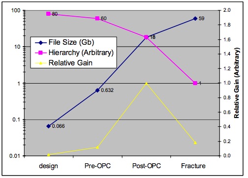
At the 45nm node an actual M1 layer from design had a file size of 0.066 Gb, however after going through pre-OPC, post-OPC and Fracture stages that same M1 layer has ballooned in file size to 59 Gb, according to a White Paper authored by four Mentor specialists (Deployment of OASIS in the Semiconductor Industry – Status, Dependencies and Outlook). The following figure shows in blue how this file size expansion happens at each stage:

File size and hierarchical content across the 4 different stages of mask data processing for a real 45nm M1 example. The “hierarchy” data is computed as the number of flat geometries divided by the number of hierarchical geometries. These results show that the post-OPC step has the highest return from an investment in hierarchical compression technology such as the OASIS format.
EDA companies rapidly adopted OASIS as a file format however it took a few years longer for the Fracture data stage to use OASIS based on survey results:
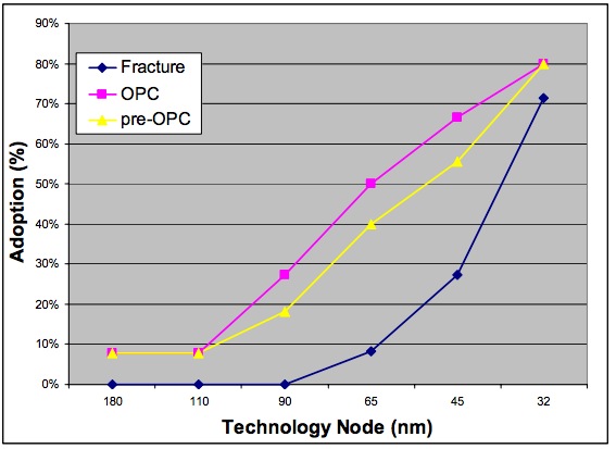
Survey results showing OASIS adoption by technology node, broken down by the data-prep handoffs. These results indicate that OASIS has been adopted by a significant fraction of companies doingOPC as early as 65nm, but that hand-off of fractured data in OASIS has lagged by as much as 2 processnodes.
Just how much compression should you expect when changing from GDS II to OASIS? The average compression is 18.57 at the design stage, and 14.24 at the post-OPC stage:
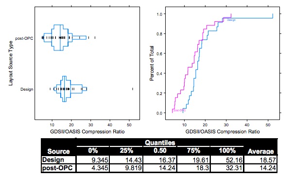
Data size savings of OASIS vs GDSII, as measured by compression ratio of the file sizes, fordesign and post-OPC layout files. Although the median compression ratios are very similar, the entiredistribution of compression rations for post-OPC files consistently shows smaller values (shifted to theleft) than the distribution for design files.
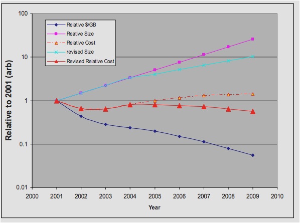
One factor that slowed adoption of OASIS from GDS II has been the low costs combined with expanding capacity of disk storage.
Summary
Work to define OASIS started back in 2001, became a SEMI standard in 2005, and was quickly adopted by EDA vendors. The post tape-out vendors are using OASIS in Pre-OPC, Post-OPC and Fracture stages to reduce runtimes by 3X and reduce file storage sizes by 3X. Old file standards like GDS II have given way to OASIS gradually over the past decade.


Comments
6 Replies to “The Need for OASIS in Post-layout IC Databases”
You must register or log in to view/post comments.