SPICE is an acronym for Simulation Program with Integrated Circuit Emphasis and represents a class of EDA software used by circuit designers at the transistor-level to predict the timing, frequency, voltage, current or power of an IC or interconnect before fabrication.
In 1971 there was a tool called CANCER (Computer Analysis of Nonlinear Circuits, Excluding Radiation) from Laurence Nagel while studying under Professor Ronald Rohrer. SPICE was then developed at UC Berkeley by Nagel in 1972 and first announced on April 12, 1973 by Professor Donald Pederson at the 16th Midwest Symposium on Circuity Theory.

Laurence Nagel, Ph.D
SPICE become widely popular because it was readily available as public domain software, you just needed to ask for it and pay a small fee to cover the cost of the magnetic tape to start using SPICE at work or school.
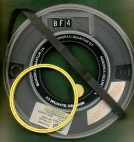
Prior to CANCER and SPICE only large semiconductor companies and military contractors had written their own circuit simulation tools that were proprietary and not for sale.

The initial approach of SPICE1 was to build a sparse matrix of node voltages and branch currents, use integration algorithms for transient analysis, and provide built-in models for semiconductor devices (Bipolar transistors, diodes, resistors, capacitors). Later, models for MOS devices were added to SPICE after David Hodges joined UC Berkeley and brought along the Shichman-Hodges model. SPICE1 was written in Fortran, used a fixed timestep, and you could simulate up to 50 nodes and 25 bipolar transistors on a CDC 6400 mainframe.
SPICE2 was released in 1975 and added features like:
- more circuit elements (MOSFET, JFET, junction diode)
- variable timestep with trapezoidal or Gear integration methods
- equation formulation
- memory allocation system
- DC analysis
- AC analysis
- Transient analysis
- Noise analysis
SPICE Inputs and Outputs
In the early days you would edit a text-based netlist to control SPICE and then view the resulting output voltage and current values as numbers, or a text-based plot on paper output or a terminal monitor. Popular text editors for SPICE netlists include vi and emacs.
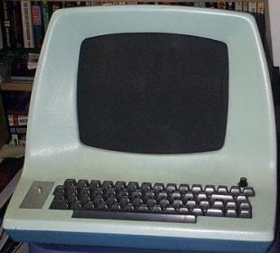
Lear Siegler ADM3A Terminal
The following deck computes the output characteristics of a MOSFET device over the range 0-10V for VDS and 0-5V for VGS.MOS OUTPUT CHARACTERISTICS
.OPTIONS NODE NOPAGE
VDS 3 0
VGS 2 0
M1 1 2 0 0 MOD1 L=4U W=6U AD=10P AS=10P
* VIDS MEASURES ID, WE COULD HAVE USED VDS, BUT ID WOULD BE
* NEGATIVE
VIDS 3 1
.MODEL MOD1 NMOS VTO=-2 NSUB=1.0E15 UO=550
.DC VDS 0 10 .5
VGS 0 5 1
.END
Input Neltlist, Source: UC Berkeley
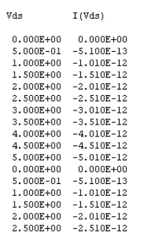
Output from a .PRINT statement
Ellis Cohen furthered SPICE 2G6 in 1983, the last Fortran release.
Thomas Quarles developed SPICE 3 in 1989 using C code plus added support for:
- MOSFET models (BSIM)
- Plotting in the X Window System
Commercial SPICE
Many software companies began offering SPICE-based and derived circuit simulators for commercial use like HSPICE from Meta-Software (acquired by Avant!, acquired by Synopsys), Spectre from Cadence and Eldo from Mentor Graphics. A list of all known SPICE simulators is found on this SemiWiki page.
Starting in 1981 EDA vendors like Daisy, Mentor and Valid (DMV) began offering schematic capture to graphically automate the task of creating SPICE netlists.
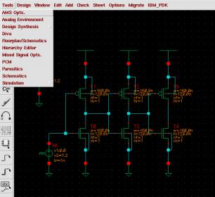
Cadence Virtuoso Schematic
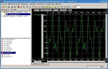
Synopsys WaveView
Traditional SPICE builds a single large matrix, while newer SPICE-like tools have been added to offer billion-transistor capacity and parallel simulation using multi-matrix techniques:
- Fast SPICE (5X to 100X faster than SPICE)
- Analog FastSPICE (up to 5X faster than SPICE, single matrix)
- Hierarchical Fast SPICE (5X to 10,000X faster than SPICE, billion-transistor capacity)
- SPICE co-simulation with HDL simulators
References
SPICE, Wikipedia.
The Life of SPICE, Laurence Nagel. September 30, 1996.
Share this post via:


Flynn Was Right: How a 2003 Warning Foretold Today’s Architectural Pivot