At SemiWiki we’ve blogged before about 3D field solvers and the different approaches that trade off accuracy, speed and capacity:
Who Needs a 3D Field Solver for IC Design?
An Affordable 3D Field Solver at DAC
Memory Cell Characterization with a Fast 3D Field Solver
A New Hierarchical 3D Field Solver
Nimbic (formerly Physware) – 3D Field Solver in the Cloud or Desktop
QuickCap for IC Extraction at DAC 2011
3D Transistors and IC Extraction Tools
How Do You Extract 3D IC Structures?
TSMC Theater Presentation: Lorentz Solution!
Nimbic (formerly Physware) – 3D Field Solver in the Cloud or Desktop
An Affordable 3D Field Solver at DAC
Why X-Fab uses 3D Resistance Extraction and Analysis
Advanced Memory Cell Characterization with Calibre xACT 3D
Reducing the Need for Guardbanding Flash ADC Designs
My question today is, “How would I measure the accuracy of my 3D field solver?”
Fortunately, the Japanese researchers at STARC have done this measurement and reported their results in a white paper that specifically looked at the Calibre xACT 3D tool from Mentor Graphics.

3D Field Solver Approaches
You have many approaches to choose from when it comes to a 3D field solver, and the following chart summarizes the most popular approaches:
[TABLE] style=”width: 500px”
|-
| 3D Field Solver
| 3D Method
| Accuracy, Capacity, Speed
|-
| Calibre xACT 3D
| Deterministic hybrid of
Finite Element Method (FEM)
and Boundary Element Method (BEM)
| Reliable, block-level, fast
|-
| Calibre xACT 3D
Reference
| Finite Difference Method (FDM)
| Accurate, cell-level, slower
|-
| Raphael
| Finite Difference Method
| Accurate, device-level, slower
|-
| Other
| Statistical
| Less accurate, device-level, fast
|-
| FastCap, HiCap
| Boundary Element Method
| Accurate, device-level, slow
|-
Creating a Reference
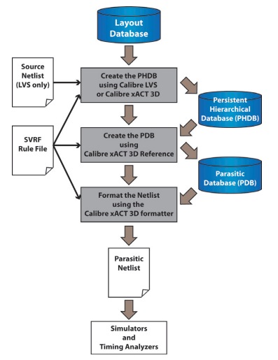
For best accuracy the reference results are created with the FDM approach of Calibre xACT 3D Reference in the following extraction flow:
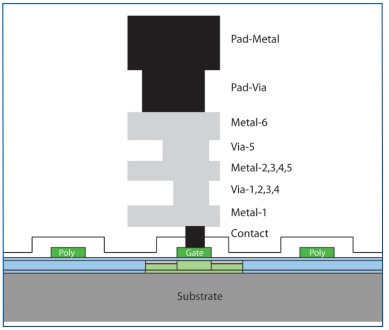
Here’s the process cross-section using a 90nm process from STARC:
Device Model Effects
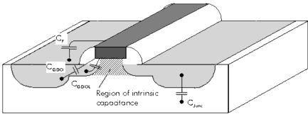
For BSIM3 the device model itself includes capacitance from gate to source or drain, shown as Cf so you wouldn’t want to include that in your parasitic extraction:
Inverter Chains
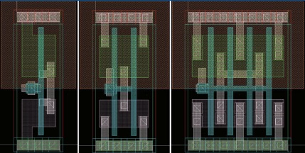
Simple inverter cells were used and connected as inverter chains with long interconnect in order to test device accuracy:

Accuracy of Calibre xACT 3D versus Reference
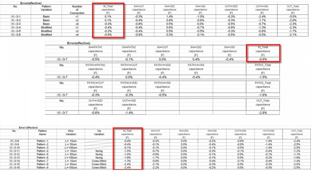
Starting with a single basic inverter the Calibre xACT 3D results were within a range of -0.5% to 0.1% of the reference, and for an inverter with long wires the accuracy was within 2.4%.
Extracting Device Capacitance
The gate to drain and gate to source capacitances are modeled by the BSIM device model itself, so capacitance C2 values should not be extracted by a 3D field solver:
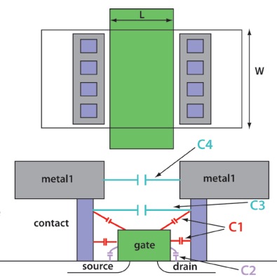
Top view and cross-section view of an MOS device with device-level capacitances
Calibre xACT 3D can either extract capacitance C2 (also called Cgdo, Cgso) or let the Device model calculate C2, so one question is, “How sensitive is my design to this C2 value compared to the total Capacitance?”
Here’s the comparison between extracting Cgdo/Cgso and ignoring it on total capacitance:
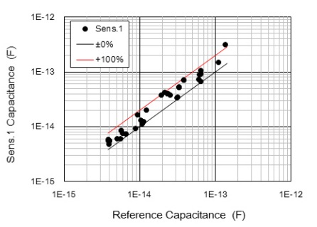
Total gate capacitance will vary by 100% on the gate net when extracting Cgdo/Cgso or not. A VCO design was designed and then parasitic capacitances extracted with and without Cgdo/Cgso values while comparing total gate capacitance on six nets:
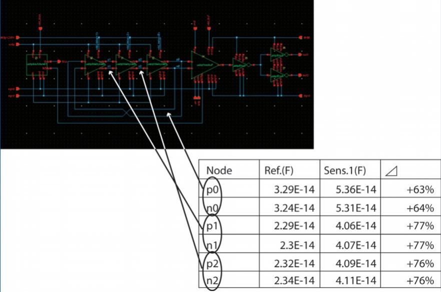
Results
Extracting capacitance values for Cgdo/Cgso then increased the total gate capacitance by 63% to 77%, which in turn decreased the maximum oscillation frequency by 10% and increased power consumption by 5%. The performance of a VCO is then quite sensitive to how you use an extraction tool, so for best accuracy the extractor should not be extracting Cgdo/Cgso values and instead allow the device model to calculate these values.
Additional sensitivity comparisons were conducted for capacitance components of:
- Cgco (C1)
- Fringing pseudo capacitance
- Metal Line to Nwell-Pwell
The 2.4% accuracy of Calibre xACT 3D result compared to a reference value was measured by using test IC layouts in a 90nm process. Calibre xACT 3D allows you to block extraction of the C2 capacitance, providing the most accurate extraction and simulation results.
Share this post via:


Comments
0 Replies to “Measuring the Accuracy of a 3D Field Solver for IC Extraction”
You must register or log in to view/post comments.