Automotive ICs have to operate in a very demanding environment in terms of both temperature and voltage ranges, along with the ability to withstand g-forces and be sealed from the elements. Not an easy design challenge. For many consumer ICs we see output drive currents on the IO pins measured in mA, however in automotive if you want your IC to drive something like a DC motor then you can expect to see values in the Amp range, big difference. Engineers at an automotive IC design group in Toshiba recently had the challenge of designing a channel brushed DC motor driver chip with specifications of:
- PWM mode: H-bridge driver
- Output current: 5A
- Low Ron: < 0.45 ohms
- Operating voltage, 4.5V to 28V
- Operating temperature, -40C to 125C
Here’s a block diagram of the Toshiba TB9051FTG chip:
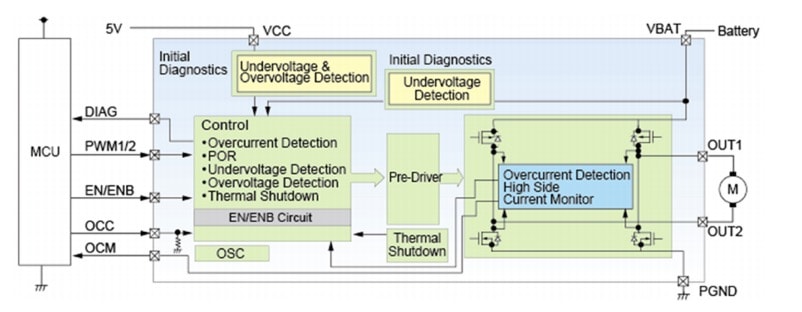
When these large output driver transistors get turned on and start to draw currents the heat levels on the chip next to these transistors begin to rise, which in turn effects the transistor performance. If your circuit simulator doesn’t take into account the thermal effects of transistors driving large currents, then your simulation results will be overly optimistic and probably won’t meet your tight specifications. Toshiba uses DMOS (Double-diffused Metal Oxide Semiconductor) transistors for the high drive output pins, and the commercial SPICE simulator that supports fully-coupled electrothermal simulation is Eldo, from EDA vendor Mentor Graphics (a Siemens business).
Having a simulator that can simultaneously account for electrical and thermal properties is really mandatory for the design of this type of automotive chip. Here’s a block diagram showing the EDA tool flow for electrothermal analysis:
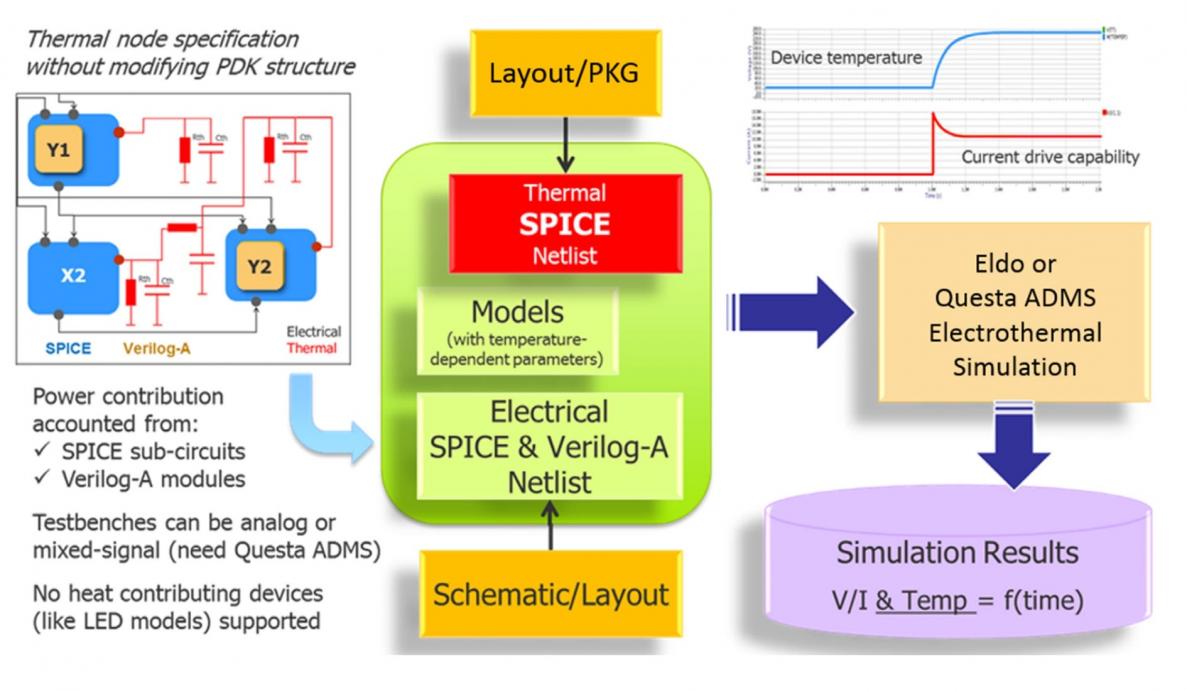
Inputs to the SPICE simulator are an extracted layout netlist, Verilog-A netlist and a thermal netlist. The Eldo simulator then produces a transient analysis showing current values and device temperature as a function of time. On this chip is a thermal unit which controls the output DMOS transistors as shown below:
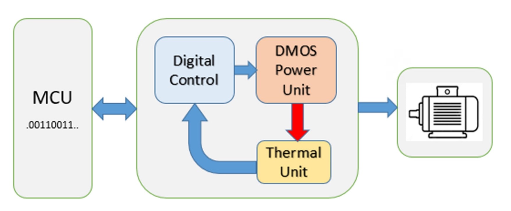
The blue arrows in the block diagram are electrical data flow, while the red arrow is the thermal flow. With the Eldo circuit simulator there is a simultaneous solver for both electrical and thermal equations, giving you results that are both accurate and fast. Other approaches that use a relaxation technique to solve electrical and thermal coupling are vastly inefficient and have much longer run times. So with the concurrency in Eldo you get to see transient analysis results that are accurate and fast for both device temperature and current drive:
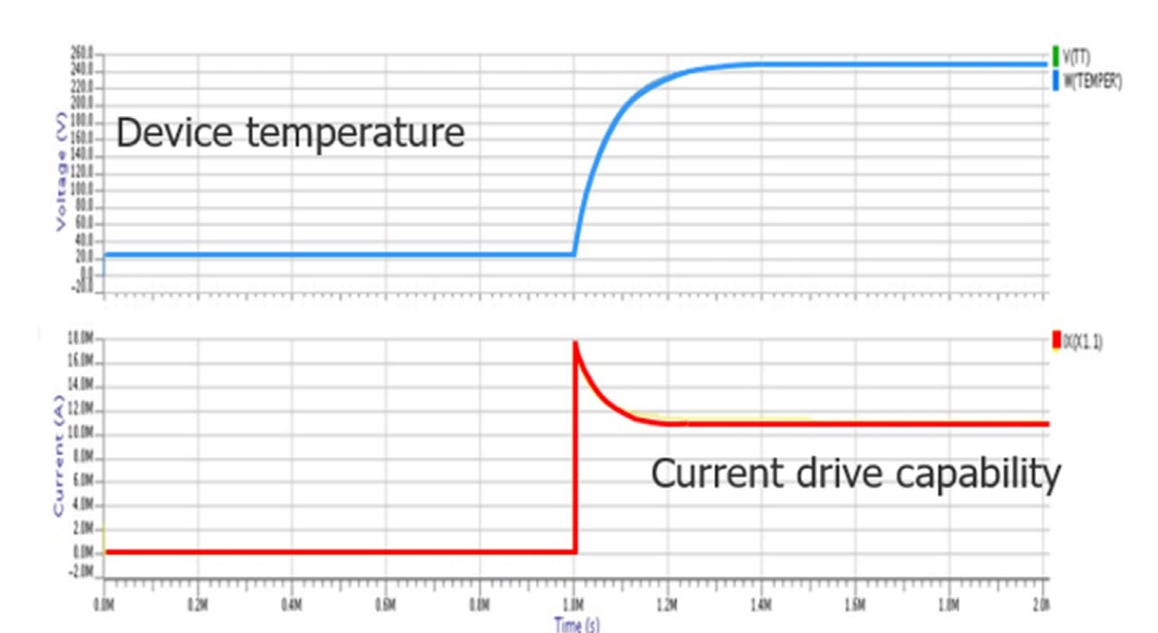
Looking at the current drive value in red we see that as the DMOS transistor turns on in the middle of the waveform there is a large increase in current, but then as the transistor heats up this current drive level tapers off to a smaller value than the peak value.
Related blog – Mentor DefectSim Seen as Breakthrough for AMS Test
Electrothermal Example
To get a grasp of how an electrothermal simulation works with Eldo let’s look at a simplified example with just three transistors that are thermally coupled:
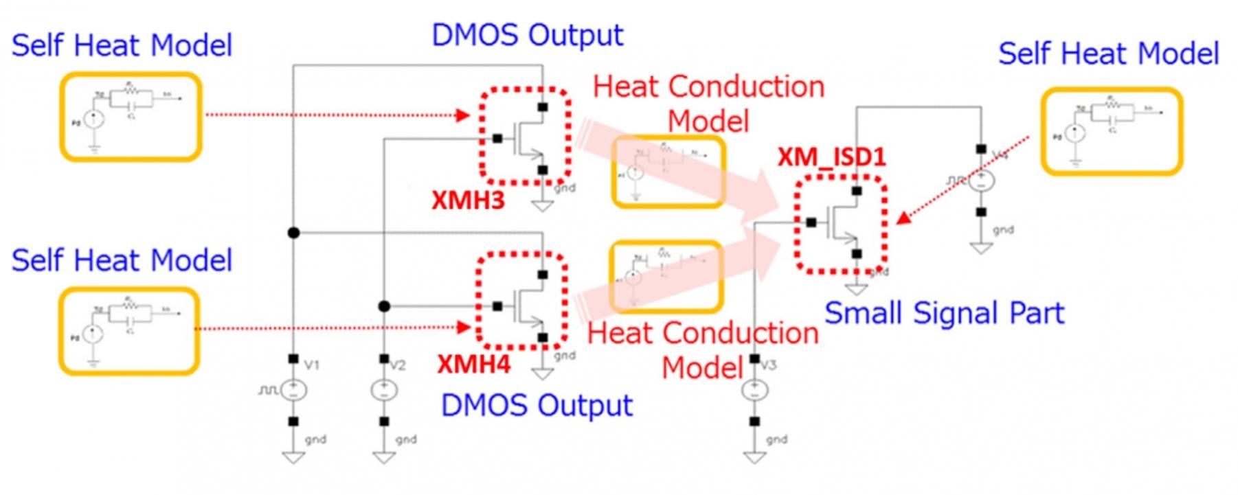
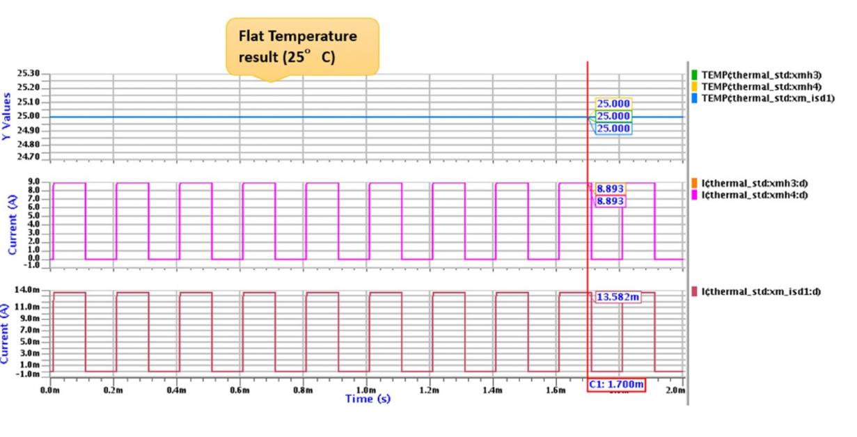
The DMOS output transistors are shown on the left as XMH3 and XMH4, where they are controlled by pulse width modulation (PWM) signals, then there’s a current sensor transistor XM_ISD1 to control the input signal of the power DMOS devices. Simulating this example using an analog solver without any thermal coupling will produce a DMOS transistor temperature (blue) that doesn’t change even as the currents are toggling (pink and red):
Simulating again but with self-heating effects turned ON produces a very different result where we can start to see the transistor temperatures dynamically moving (blue yellow) as currents are toggling (pink and red):
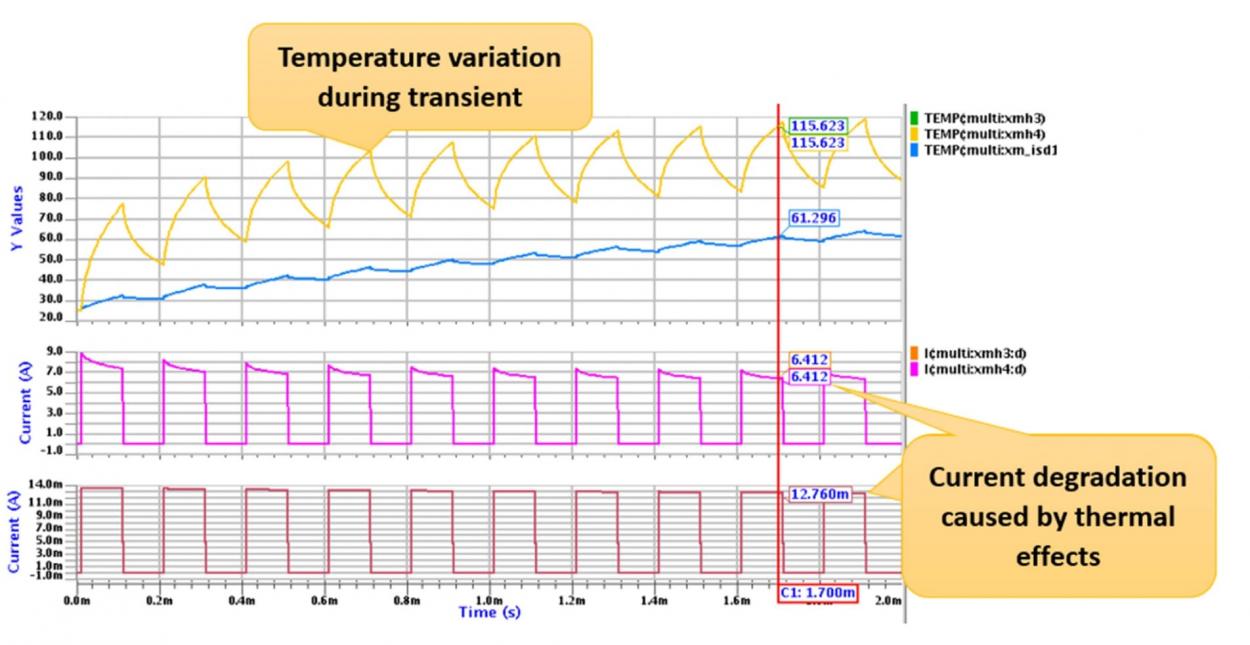
Notice that the current shown in the middle curve (pink) has a high value that is tapered lower than its peak value, just what we’d expect to see as the higher temperatures begin to reduce the drive current levels.
Simulated Versus Silicon Measurements
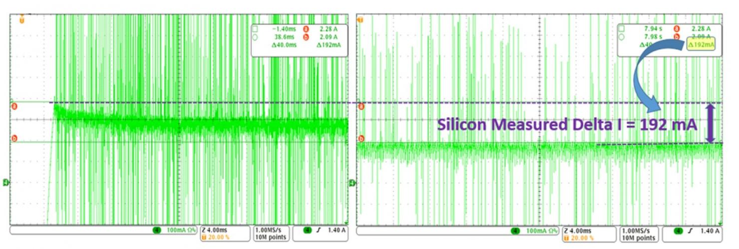
The ultimate accuracy test of any SPICE circuit simulator is measuring silicon results on the bench and comparing them versus the simulated values. Toshiba engineers did this comparison and found that Eldo was producing current results within 1.5% of measurement using a Tektronix MSO405.4 oscilloscope during two time windows: 0 to 4ms (left), 86-90ms (right)
So now we know that Eldo does accurate electrothermal simulations, but what about the speed of circuit simulation? Mentor offers two speed versions of their circuit simulator, and on this particular chip simulating for 90ms of transient the run time comparisons for electrothermal simulations are:
- Eldo with 1 core, 38h 48m
- Eldo Premier with 1 core, 11h 50m
- Eldo with 8 cores, 16h 38m
- Eldo Premier with 8 cores, 7h 31m
Summary
If you need electrothermal simulation results accurately and fast then use Eldo, for faster results try Eldo Premier, and for the fastest run times use Eldo Premier with 8 cores. The chip designers at Toshiba have shown that you can expect simulated results to be within 1.5% of measured silicon, so Eldo has a very accurate electrothermal simulator that is ready to go on any circuits that have high current drive and localized heating within the IC.
White Paper
There’s a 10 page white paperon this topic online that requires a brief registration form.
Share this post via:


Comments
20 Replies to “Electrothermal Analysis of an IC for Automotive Use”
You must register or log in to view/post comments.