Spice circuit simulation remains the backbone of IC design validation. Digital cell library developers rely upon Spice for circuit characterization, to provide the data for Liberty models. Memory IP designers utilize additional Spice features to perform statistical sampling. Analog and I/O interface designers extend these requirements into frequency-domain analysis, using parameter sweeps. Across all these domains, focusing on optimizing Spice simulation throughput is crucial.
Yet, technology trends are exerting pressure on circuit simulation performance. The number of PVT corners is growing significantly. From a design perspective, the number of operating voltage conditions is increasing, as dynamic voltage frequency scaling (DVFS) methods are more widely applied. The number of process-based corners is also growing, driven in large part by the additional variation associated with lithographic multi-patterning overlay tolerances. Each multi-patterned layer now exhibits a variation range in coupling capacitance between adjacent wires which have been decomposed to separate masks for the layer.
And, a major increase in the number of layout-extracted parasitic elements has emerged in current technologies, due to the addition of dummy devices adjacent to active transistors, the additional of local interconnect layers (prior to contacts and M1), and the increased number of metal and via layers. Specifically, these parasitic elements have a growing impact on circuit performance, as scaling of the physical width and cross-sectional area of the associated wires and vias has continued.
All these factors have increased the Spice simulation workload. And, the annotation of extracted parasitics to the original schematic netlist reduces the simulation performance substantially.
To address these trends, Spice simulation tools have incorporated performance enhancements – e.g., parallel thread execution, “fast” execution using simplified device models, and “event-driven” solvers for analysis of sparsely-active circuits. Yet, these approaches all have an associated cost, whether it be an accuracy versus performance tradeoff, or simply the licensing costs for these different tools to fulfill the simulation requirements.
Fundamentally, the first step should be to optimize the parasitic-annotated netlist, to get the best overall performance regardless of the simulation method. Although layout extraction tools offer options to adjust the accuracy and size of the resulting parasitic model, an attractive methodology would be to extract at the highest accuracy setting, then subsequently optimize this netlist for the target applications.
At the recent DAC conference, I had the opportunity to meet with Jean-Pierre Goujon, Application Manager at edXact. He was enthusiastic about two recent events:
(1) the increasing customer adoption of their parasitic reduction technology, and
(2) the recent acquisition of edXact by Silvaco, which will further expand their market presence (and from Silvaco’s perspective, continue their recent emphasis on broadening their product portfolio)
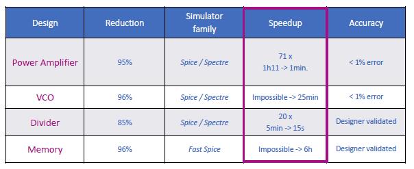
The focus for edXact has been on algorithmically-robust methods for reduction of large parasitic networks to improve Spice simulation throughput, while maintaining (user-controlled) accuracy of the results. Their approach applies rigorous model-order reduction methods, preserving input/output pin impedance, pin-to-pin resistance, and pin-to-pin delay. The netlist size reduction and thus the simulation speedup examples Jean-Pierre highlighted were impressive – please refer to the figure below.

Note that both full and “fast” Spice simulation tools reap the benefit of the optimized netlist. (According to Jean-Pierre, a “typical” runtime for model-order reduction on an IP block would be about one CPU-hour.)
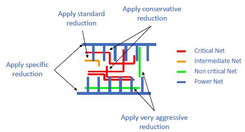
There are additional edXact options available to designers, to further enhance simulator performance. For example, for some (digital cell) simulation applications, there are less stringent characterization requirements – the accuracy required for delay arcs in DFT scan mode come to mind. Reduction options can be selectively set by the designer for different nets. As illustrated below, specified “critical nets” maintain the highest accuracy (most conservative reduction), while non-critical nets can be more aggressively reduced.

I tried to trip up Jean-Pierre, asking “What about the various data formats used by different Spice simulation and extraction tools?”
“No problem.”, he replied. “We support all major simulator and parasitic netlist formats for actives and passive elements – Spice, Spectre, DSPF, SPEF, SPF, CalibreView, with R, C, L, and K parasitics. The tool is easily integrated into existing design platforms and flows.”
He added (with a smile), “And, don’t forget the temperature coefficients of resistance on extracted wires – TC1 (first order) and TC2 (second order). We adjust these coefficients on the reduced netlist to maintain the same overall temperature dependence.”
I then posed my toughest question, “How would a customer ‘qualify’ the netlist reduction technology in their design environment?”
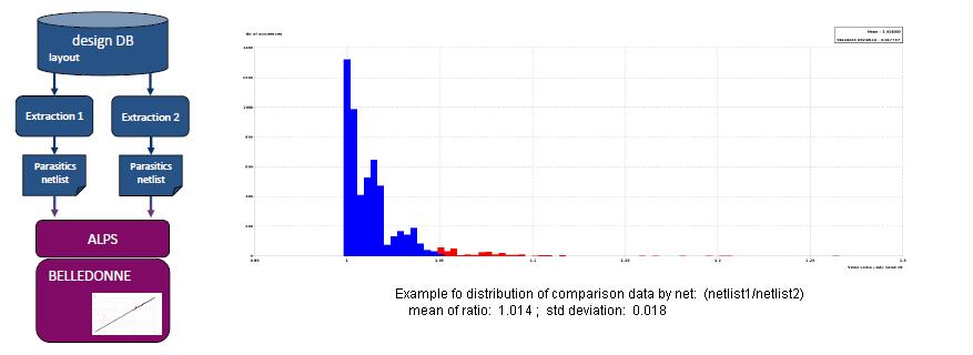
Jean-Pierre answered, “We have a separate tool for qualifying results, providing users with visual, analytical feedback on the comparisons between the original and reduced netlists. We compare the effective delay between pins. And, the pin-to-pin resistance is also a critical metric.”

When forecasting the Spice simulation resources required for your next design project — i.e., software licenses, server CPU’s and memory, target throughput/schedule — it would be appropriate to ensure that optimized post-extraction netlists are the norm for your design flows. An investment in model-order reduction technology will very likely provide an attractive ROI, with minimal impact on the accuracy of the simulation results.
For more information on the edXact reduction technology, please refer to this link.
-chipguy
Share this post via:

![SILVACO 051525 Webinar 400x400 v2[62]](https://semiwiki.com/wp-content/uploads/2025/04/SILVACO_051525_Webinar_400x400_v262.jpg)


Comments
0 Replies to “It’s Time to Put Your Spice Netlists on a Diet”
You must register or log in to view/post comments.