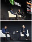
In a keynote delivered at this year’s Siemens EDA User2User event, CEO Mike Ellow presented a focused vision for the evolving role of electronic design automation (EDA) within the broader context of global technology shifts. The session covered Siemens EDA’s current trajectory, market strategy, and the changing landscape of semiconductor and systems design. Since Mentor Graphics became part of Siemens AG, the User2User event has become the annual opportunity to gain holistic insights into the company’s performance and strategic direction.
Sustained Growth and Strategic Investment
Siemens EDA has demonstrated strong growth over the past two years, both in revenue and market share. The company has responded by increasing R&D investment and expanding its portfolio. Notably, over 80% of new hires in fiscal year 2024 were placed in R&D roles, underscoring a strategic emphasis on product and technology development.
This growth comes during a period of industry consolidation and transformation. Without its own silicon IP offerings, Siemens is reinforcing its position around full-flow EDA, advanced simulation, and systems engineering. These areas are seen as key differentiators in a market where integration across domains is increasingly essential.
Extending Beyond Traditional EDA
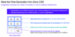
Mike outlined Siemens’ expanding footprint into areas traditionally considered outside the core EDA domain. The $10.5 billion acquisition of Altair, a multiphysics simulation company, along with strategic moves into mathematical modeling, reflects a long-term strategy aimed at enabling cross-domain digital engineering. These capabilities are becoming increasingly important as products evolve into complex cyber-physical systems.
The company’s parent, Siemens AG, continues to invest heavily in digitalization, simulation, and lifecycle solutions. EDA now plays a central role in this technology stack, bridging the gap between silicon and the broader systems in which it operates.
Software-Defined Systems and AI as Central Drivers
At the heart of Siemens’ vision is the recognition that software is now the primary driver of differentiation. This shift means traditional hardware-led design processes must be restructured. The industry is moving toward a software-defined model, where silicon must be architected to support flexible, updatable, software-driven functionality.
This transition includes integrating AI directly into the design process—both as a capability within the tools and as a requirement for the end products. AI is accelerating demand for compute and increasing design complexity, but it also enables new methods of automation in verification, synthesis, and optimization. Siemens EDA is investing on both fronts: helping customers build silicon for AI, while embedding AI into its own design tool flows.
Multi-Domain Digital Twins
In today’s cyber-physical products—such as electric vehicles or industrial control systems—software and hardware must co-evolve in lockstep. The traditional handoff model, where completed hardware designs are passed to software teams, often results in inefficiencies and functional mismatches.
Instead, Siemens is promoting the use of multi-domain digital twins—integrated system models that span electrical, mechanical, manufacturing, and lifecycle domains. These models enable real-time collaboration and help prevent costly late-stage trade-offs. For example, a software update could inadvertently impact braking, weight distribution, and overall performance, resulting in a significant drop in range. A tightly coupled digital twin helps identify and mitigate such cascading effects before deployment.
Silicon Lifecycle Management and Embedded Monitoring
Beyond early design, Siemens is advancing silicon lifecycle management (SLM) by embedding monitors directly into chips to collect real-world operational data throughout their lifespan. This telemetry, feeding continuously into the digital twin, enables predictive maintenance, lifecycle optimization, and performance tuning as systems age.
This approach transforms silicon from a static component into a dynamic asset. Over-the-air updates, anomaly detection, and usage-aware software adaptation become feasible, improving product reliability and long-term value.
AI Infrastructure and Secure Data Lakes
To manage the escalating complexity of software-defined, AI-powered electronics, Siemens is building a robust AI infrastructure anchored in secure data lakes. These repositories aggregate verified design, simulation, and test data while maintaining strict access control—crucial for IP protection.
Domain-specific large language models (LLMs) and AI agents are being trained on this data to automate tasks such as script generation, testbench development, and design space exploration. Siemens is developing a unified AI platform to further support automation, decision-making, and cross-domain intelligence throughout the design lifecycle. The platform will be formally announced in the months ahead.
3D IC, Advanced Packaging, and Enterprise-Scale EDA
A key focus is the rise of 3D ICs and heterogeneous integration, from chiplets to PCB-level packaging. Siemens is enhancing its toolsets to support the convergence of digital and analog design, using AI-driven workflows to increase scalability and accuracy in these complex architectures.
These initiatives support Siemens’ broader push toward enterprise-scale EDA—democratizing access to advanced design tools through cloud platforms. These environments empower distributed teams, including less-experienced engineers, to collaborate on sophisticated designs. AI-powered automation bridges skills gaps, accelerates time-to-market, and enhances design quality.
Navigating Geopolitics and Sustainability
Mike also addressed external forces reshaping the semiconductor industry, including geopolitical pressures and the growing need for sustainability. Regionalization is accelerating, as countries invest in domestic design and manufacturing to mitigate supply chain risks and safeguard IP.
Meanwhile, AI and ubiquitous connectivity are driving compute demands beyond traditional energy efficiency gains. Siemens EDA is responding with low-power design methodologies, energy-efficient architectures, and system-wide optimization strategies that combine AI with simulation to reduce power consumption.
Summary
The central message of the keynote was that the future of electronics is AI-powered, software-defined, and silicon-enabled. For EDA providers, this means going beyond traditional design boundaries toward a full-stack, lifecycle-aware development model that integrates software, systems, and silicon from the outset.
Siemens EDA is positioning itself as a leader in this transformation—through comprehensive digital twins, embedded silicon lifecycle management, secure AI infrastructure, and cloud-enabled, democratized design platforms.
Also Read:
EDA AI agents will come in three waves and usher us into the next era of electronic design
Safeguard power domain compatibility by finding missing level shifters