The GlobalFoundries DRC+ platform is one of the most innovative DFM technologies and was well represented at #48DAC. In case you missed it, here is a reprint of a DRC+ overview from GFI just prior to #48DAC:

DRC (Design Rule Constraints) are the fundamental principles in constraining VLSI (Very Large Scale Integration) circuit designs to standardized physical and electrical manufacturability criterion.
Today’s component miniaturization and density technologies require continual reassessment of best practice applications to keep design geometries aligned with realistic manufacturing capabilities. Two-dimensional DRC layout patterns may prove to be mathematically and layout rules compliant. But, when they are applied at the extremes of the manufacturing process tolerances, lithographic printability issues still arise. DRC+ is a new methodology that can be implemented in identifying the issues around complex process methods.
DRC+ pattern based rule deck provided by GLOBALFOUNDRIES is a cutting-edge application that can not only identify the 2D pattern anomalies early on; it can efficiently identify these anomalies during the all stages of the design flow. DRC+ functions in the same fashion as traditional design constrained applications. However, it adds the function of associating a 2D pattern with each constraint which acts as a filter to localize where the constraint is applied.
The result of this functionality is that the DRC tool, running a DRC+ rule deck, will enforce tighter constraints only where the anomalies occur. For this discussion tip-to-side patterns are the subject.
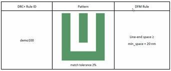
An example of this implementation is shown in Figure 1, which enforces a tighter min-space +20nm line-end space constraint where the U-shaped pattern is found. DRC+ operates strictly on design geometries without any intrinsic understanding of the underlying manufacturing technology process. Therefore, the effectiveness of DRC+ depends heavily on the quality of the rule deck.


A Brief Overview
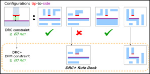
Figure 2 is an example of how DRC+ applies a “preferred” rule constraint to tip-to-side geometry. Each DRC+ rule includes a specific tip-to-side pattern, and a preferred rule, which has a more stringent constraint to be applied in that pattern situation. This example uses tip-to-side patterns that vary due to the surrounding context. In this case, the standard DRC rule specifies a constraint of ≥ 60nm, while the DRC+ rule deck adds a more stringent constraint of ≥ 80nm. A patterns that does not pass the standard DRC rule, will have the DRC+ rule applied.
One way to create DRC+ rules is to identify hotspots using printability verification simulation. Once identified, a DRC+ rule is crafted to disallow the problematic pattern in design. The DRC+ methodology employs an algorithmic approach to creating rules. Rather than using a hotspot as a starting point, it approaches the hot spot from the perspective of design, design style, and design variability to establish at the outset which patterns should be considered for DRC+ rules1. The result of DRC+ analysis is hot patterns rather than hotspots. This provides effective screening while enabling much higher efficiency and throughput than litho simulation of an entire chip.
A Bit More Detail
DRC+ uses a series of steps to identify pattern configurations. The first step is to develop situation classes. These are determined by extracting patterns from representative designs (see Figure 3) and developing a histogram of the situation classes. These classes can then be evaluated based upon permutations and occurrences.

The next step is to determine which of these situation classes have lower than average printability. These are the classes that, based upon the required constraint to ensure printability, become candidates for DRC+ rules (In the above graphic, it happens to be the tip-to-side distance). Then, a metric called Design-Induced Edge Printing Variability (DIEPV) is used to determine the printability of each class. DEIPV essentially represents printing error over the process window for a given situation—the greater the magnitude of DIEPV, the more printing error is likely.
Now, one must determine which situation classes are candidates for DRC+ rules. In the above case, a simple threshold algorithm can be implemented comparing the DIEPV statistics of each situation class to the values of the overall layout. Once the algorithm has been applied the data can be displayed graphically for analysis (see Figure 4).

Tool Implementation
DRC+ is compatible with both traditional and cutting-edge generation of EDA (Electronic Design Automation) tools. For this article, we will use Calibre® as an example. Figure 5 shows the error makers, DRC+ rule in question and its context (i.e., its situation). The equation-based DRC capability of Calibre® also provides specific hints on how to fix the violation. Where the physical verification platform is integrated into the physical design environment, most of the repairs can be done automatically by the physical design tool itself, such as the router.

Conclusion
DRC+ is a new methodology that algorithmically characterizes design variation through pattern classification. A traditional design rule is used to identify all design structures that share a common configuration. Then the 2D geometric situations (pattern variations) around the configuration are extracted and classified. Since all such classes share a common configuration, each situation class represents design variations of the basic configuration.
DRC+ uses statistics derived from measurements of the situation classes as an alternative to simple CD (critical dimension) or EPE (edge placement error) thresholds used in classic printability verification. By identifying which situation classes have bad printability statistics, we can algorithmically find DRC+ rules.
The benefits of DRC+ are gaining tremendous industry momentum as the world’s leading EDA suppliers are already releasing development tools that support GLOBALFOUNDRIES DRC+ rule sets in 28nm.
Tools that provide fast pattern matching capabilities make implementation of DRC+ straightforward. For the user it is mainly a matter of updating the standard DRC rule deck with the expanded DRC+ pattern-based rule deck provided by GLOBALFOUNDRIES. Performance is on a par with traditional DRC runs.
The GFI Concurrent Newsletter is HERE. There is a video presentation of DRC+ HERE.
Share this post via:


The Foundry Model Is Morphing — Again