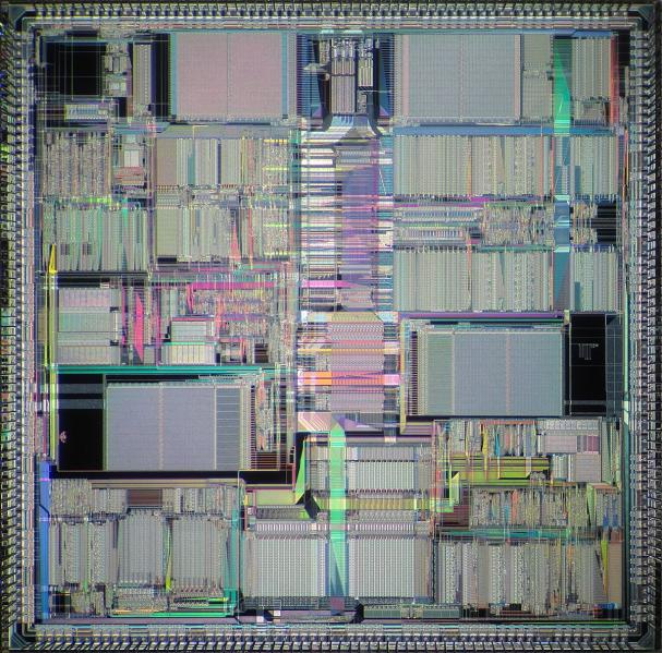
In late 1986 the Layout Project Leader of DSP96000 got married and left for a 6 months’ vacation so I inherited the biggest chip MSIL had in stock. Floorplanning such size chip was a challenge from day one. Even the 68030 SUN workstation was too slow. I started to ask around and going to demos for any other possible tool that can help me do my job. Our CEO came one night to see “how it’s going” and I was “routing” listening to music. He stayed about 15 minutes behind my back in which time I was capable to route 3 (three) signals in top level. I had a list of about 57,000 signals so he made the calculation that if I work 24 hours will be done way after tapeout time. He “empowered” me to find a solution “outside the box” even if it could be against Motorola policy.

I knew about a revolutionary tool called BRP (Block Place & Route) from ECAD, later CADENCE. The issue was not only software but hardware. The SUN on 68000 family was too slow and limited on what it can handle in DRAM and disk. The RISC processors machines were available, but it was not a Motorola chip in it ☹. Guess what, I sold the idea to our CEO and requested a RISC machine with 4 disks of 1 Gb each. It was approved immediately and the Israeli distributor, who used this machine for demos only 2 weeks earlier, had to bring it in MSIL and install it in record time.
We contacted ECAD/Cadence and we got again from UK another great AE, Steve Upham. He planned to stay for 2 weeks and stayed for 5 months. The biggest power of this software was that all signals will be routed with “preplanned” constraints and it knew how to maintain metal direction. This means new flow: each circuit owner of a block will provide a list of signals with EM/IR requirements (widths and currents) , and the layout person will ensure all applied based on architecture. The challenge was to deal with power grid issues, each block being connected many time to the same supply. All lines were “symbolic” in routing so easy to move from channel to channel or just manipulate. Once happy with the location you pushed the “compaction” button and all becomes real WIDTHS with proportional number of VIAS, and this was in 1988.
It was looking promising as we succeeded the first trial in 3 weeks, routing about 50,000 signals in 3 layers. Now the problem was how to import/export the GDSII data from/into CAECO where we need it for the real chip. CAD came to rescue again, Nachshon Gal worked with me to generate empty boxes of the real layout containing only the pins of all blocks so the total data we use in top level has only boundary and routing pins! We invented blocks ABSTRACTs in 1988. Steve and Nachshon had to rewrite a new interface and break down the final data from BPR into 2 pieces and reassemble it in CAECO. Even with abstracts the data was too big for the translation engine. One cool feature to reduce data in BPR was to reduce jogs and jumpers so smooth planning and clean channel reduced the final data. Win / win situation, smaller chip and smaller data for tools to handle.
Once we figured out that data size could be an issue, we looked at planning final GDSII verification. Remember all as FLAT in 1988 so the data footprint was very big for verification and virtual memory needed temporarily for DRC and LVS was also big. We envision that our chip will be 3×4 of the previous chip in area so we multiplied everything by 12. We did a local benchmark and found out that the only way to run this data size will be on the IBM servers in Austin, Texas, Motorola Semiconductor headquarters. We spend some effort and after one month of trials figure out what do we need for final verification. We booked 2 years in advance the servers, the virtual memory and disk needs. It proved to be a good proactive action and we tapeout on the promised day. This was another “non-layout” interesting task.
As the DSP requires a lot of Datapath blocks for Address Controllers, Multipliers, Adders, etc., we had to find ways to automate this type of layout blocks. We developed special cells for each function but adding a way to deal with last minute ECO (Engineering Change Order) was a priority in our minds. After the TEXT layer used in standard cell libraries the taste for “smarter automation” grew. We invented text layers for everything: contacts, diffusion, implants, and vias and metals. We developed a datapath programmable software that we called STDGEN, or Standard Generator. We built cells full with all layers and when ready DRC/LVS clean we changed the real layers in text one. Based on the needed functions from each cell, STDGEN was replacing the text layer with the real one and run the new verification versus the new netlist. No change in area, all external pins maintained, no possible errors and the final “coding” could come one day before final chip verification.
On this one I worked with Eythan Weiberger and other CAD guys… I was involved only in the specification stage and chip level verification as other people in the team helped CAD in this case. For this chip we spend approximatiely 300 man/months layout and about the same effort for circuit and system design and we were on schedule as planned 3 years earlier by Ika Reuveni, the original layout project leader. How is this to invent new things “as” and “when” you need them? A big part of doing all this was the unconditional support from management and all adjacent groups. It was challenging, fun, and many times exhausting but we never gave up.
One interesting fact little known to the world outside Motorola Semiconductor Israel and Cadence Israel. Around 1988 CADENCE released the first version of OPUS. Once the first customer (MSIL) bought a CADENCE license, they decided to hire a salesperson and an AE for support. But OPUS software was about 500 Mb and CADENCE did not have such a big computer to handle it. Cadence came to MSIL and negotiated to put the OPUS corporate software on my machine (which was at that time 4x1Gb disks). Every time CADENCE needed keys to enable a new customer to use any OPUS software, they will send by fax the CPU ID and I will generate the license keys. This enabled me to know more people from other Israeli companies, sometimes competitors, a little different job than layout designer duties.
Dan Clein
CMOS IC Layout Concepts, Methodologies and Tools
Also Read: Is there anything in VLSI layout other than pushing polygons? (2)
Share this post via:


TSMC vs Intel Foundry vs Samsung Foundry 2026