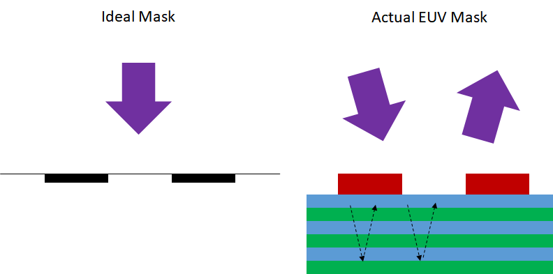
As EUV lithography is being targeted towards pitches of 30 nm or less, fundamental differences from conventional DUV lithography become more and more obvious. A big difference is in the mask use. Unlike other photolithography masks, EUV masks are absorber patterns on a reflective multilayer rather than a transparent substrate. Most articles on EUV lithography do not go into the details that SPIE papers do [1,2]. Figure 1 shows the fundamentally different aspects of EUV masks.
Figure 1. An EUV mask differs from an ideal mask in that the absorbers partly transmit EUV light into the multilayer substrate, which then reflects the light back through the absorbers for a second pass.
EUV masks are essentially like attenuated phase shift masks, where the phase shift is very different from the ideal 180 degrees. In fact, the phase shift depends on the illumination angle as well as the absorber thickness, and a phase shift comes from propagating through the multilayer as well. Since all illumination is from one side, shadowing is a natural consequence as well [1].
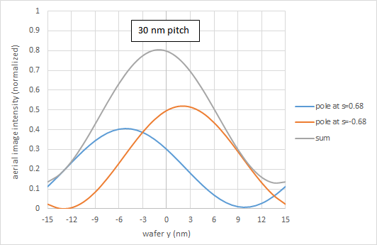
For the tighter pitches, dipole illumination is used. For the case of EUV mask illumination within the plane of incidence, this means one illumination angle will be larger than the other. This results in the image from one angle being dimmer and shifted in phase, i.e., position, relative to the other (Figure 2). For this image calculation, the absorber was assumed to be 60 nm thick, with an optical constant of 0.94+0.04i, and the multilayer reflectance at 13.5 nm wavelength was obtained from the CXRO database [3].
Figure 2. A dipole illumination tuned for 30 nm pitch would produce a symmetric image for an ideal mask, but not so for an EUV mask.
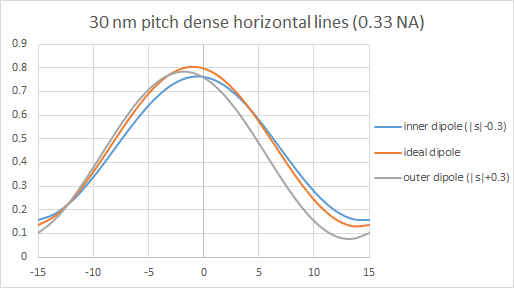
It’s apparent that the image is displaced by an amount that depends on the illumination angle. Figure 3 shows that dipoles spaced apart with different distances from the pupil center produce different shifts. The closer the two poles are to the center, the less asymmetry there is, as the illumination angles differ by less.
Figure 3. Different dipole illumination positions produce different EUV image shifts. The closer to the center, the less disparity between the images of the two pole angles, and therefore the less asymmetric the image.
The pattern shifts are more severe for tighter pitches. Therefore, it should not be a surprise to expect growing consideration, for example, of different absorbers in “next-generation” EUV masks.
References
[1] S. Sherwin et al., “Advanced multilayer design to mitigate EUV shadowing,” Proc. SPIE 10957, 1095715 (2019).
[2] E. van Setten et al., “Multilayer optimization for high-NA EUV mask3D suppression,” Proc. SPIE 11517, 115170Y (2020).
[3] https://henke.lbl.gov/optical_constants/multi2.html
Share this post via:


Semidynamics Unveils 3nm AI Inference Silicon and Full-Stack Systems