AMS IC designers have a lot to think about when crafting transistor-level designs to meet specifications and schedules, so the most-used tool in their kit is the trusted SPICE or FastSPICE circuit simulator to help analyze timing, power, sensitivity and even device noise. I just did a Google search for “device noise analysis ic” and the first five of ten search results all have links to Mentor Graphics, so that led me to read their recent White Paper entitled, “Ten Common Device Noise Analysis Mistakes“.
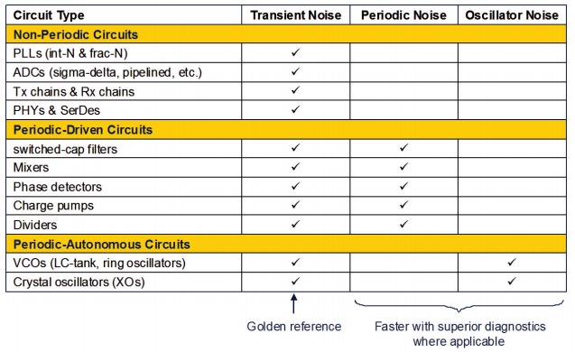
The three types of Device Noise Analysis are listed in this table for a variety of AMS circuits:

The basic idea is to run the appropriate type of noise analysis depending on the circuit type. If you are using a standard SPICE circuit simulator, then the following list of 10 mistakes will be helpful to avoid, or you could consider using the Analog FastSPICE(AFS) tool from Mentor that is equipped to handle each issue.
1. Insufficient Transient Accuracy
An AMS circuit may require 80 dB to 120 dB of dynamic range, however the default SPICE tolerances typically default to a reltol=1e-3 value, providing just 60 dB of dynamic range. For each 20 dB of dynamic range then tighten reltol by a factor of 10X smaller.
2. Periodic Noise Analysis with Too Few Sidebands
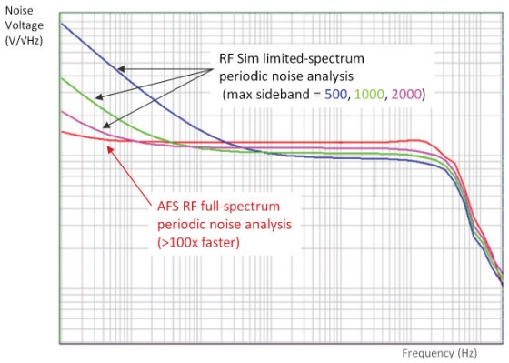
The default number of sidebands in SPICE for periodic noise analysis is under 50, however for 45 nm and smaller geometry process nodes you will want to use greater than 1,000 sidebands. Traditional SPICE run times increase quadratically with the number of sidebands, so you can quickly run out of RAM. The magic sauce with AFS RF allows you to run full-spectrum device noise analysis, which has an accuracy equivalent to an unlimited number of sidebands per run.

Switched-Capacitor Filter Noise Voltage Comparison
3. Simplifying Circuits for Periodic Noise
Using SPICE for periodic noise analysis consumes too much RAM, so you may be tempted to just simplify your netlist by removing transistors and other elements. The big downside is that you could make a mistake in your reduced netlist, plus you are taking up valuable engineering time. With the AFS RF tool you can simulate circuits with more than 100K elements, a much easier approach.
Related – Full Spectrum Analog FastSPICE Useful for RF Designs on Bulk CMOS
4. Not Including Parasitics in VCO device noise analysis
With limited capacity in SPICE it’s tempting to simulate a VCO using a pre-layout netlist with no parasitics, although the values your simulation returns aren’t really accurate without parasitics.
5. Using Oscillator Noise instead of VCO noise
Having a circuit simulator that can perform only free running oscillator noise is quite a limitation if you really have a voltage controlled oscillator (VCO), because the analysis results are quite different. The AFS RF tool handles both free running oscillator and VCO noise analysis.
6. Manually Analyzing VCO Sensitivity
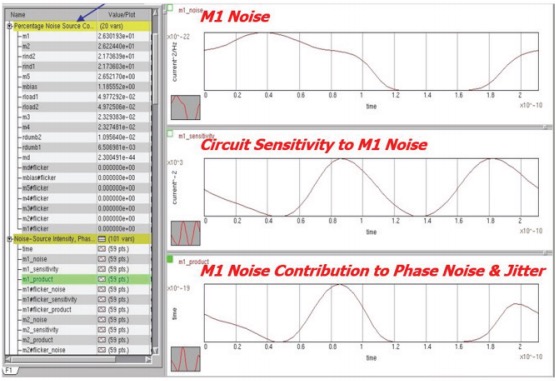
One part of optimizing a VCO is to minimize phase noise, and you can perform this analysis manually by taking more time, increasing the possibility of errors, and really only approximating the values. A more elegant approach is to visually see the instantaneous noise from every device as it contributes to the VCO output noise. Here’s what that analysis looks like with AFS RF for the noise intensity, sensitivity and jitter:

VCO Noise Contribution Sensitivity
7. Not Updating Transient Noise for Every Device at Every Time Step
A traditional transient noise simulator may update the random device noise injection at fixed time intervals, but not at every simulator time step, causing inaccuracy. With the AFS simulator you will see accurate transient noise results by injecting noise at every time step.
8. Setting Transient Noise NoiseFmax Too Low
With SPICE you can set the noisefmax simulator setting to trade off runtime and accuracy, choosing a smaller noisefmax gives a shorter runtime but with lower accuracy, choosing a higher noisefmax gives better accuracy but at slower runtimes. It’s hard to tell when you’ve made the right trade off with noisefmax. Since AFS uses the full noise spectrum from noisefmin to noisefmax there is no truncating the device noise spectrum.
Related – DAC Update on IC Design Tools at Mentor
9. Setting Transient Noise Tstop Too Short
Users get to set their tstop value controlling how many cycles a simulation runs, but choosing a value that is too short means that the results could be statistically uncertain. When using the AFS simulator for transient noise analysis you get a recommended tstop value that gives the desired statistical confidence level.
10. Post-Processing Mistakes
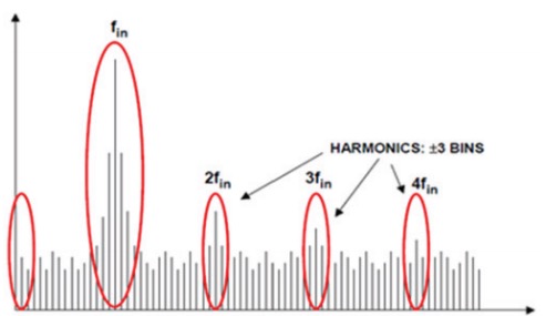
Many AMS designs have performance metrics measured in the frequency domain, while a transient noise analysis is in the time domain so you have to use a fast Fourier Transform (FFT) post-processing on the data. Be cautious about post-processing because it impacts accuracy by:
- Extra spectral leakage beyond 2.5 FFT bins
- Some signal frequencies are not perfectly centered
- An FFT window which doesn’t minimize spectral leakage
- Using MATLAB default FFT windows

Excessive Spectral Leakage
With AFS there’s CalcPad that does the post-processing of transient noise waveforms to ensure correct FFT-based results.
Summary
Device noise analysis is required for AMS IC designs to reach performance goals but there are many pitfalls when using a traditional SPICE circuit simulator. Choosing a SPICE circuit simulator like Analog FastSPICE from Mentor Graphics will help you to do that safely and quickly. Read the complete 6 page White Paper here.


Comments
0 Replies to “Device Noise Analysis, What Not to Do for AMS IC Designs”
You must register or log in to view/post comments.