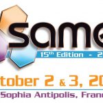
This is the 15[SUP]th[/SUP] anniversary for the SAME Conference, dedicated to innovation on Microelectronics. Sophia-Antipolis is not only close to Mediterranean sea, but also at the heart of Telecom valley in south of France, with Texas Instruments design center dedicated to Application Processor design (OMAP), Cadence research center (managed by Jacques-Olivier Piednoir) developing Virtuoso Full custom layout edition tools (along with other team in India and the US), ST-Ericsson and many more. This area is a nice place to attract high level engineers, this explains why many companies, including ARM, Cambridge Silicon Radio (CSR), Intel, NVIDIA, Maxim, Mentor Graphics and Synopsys have a subsidiary here. To see the full company list, just go here. If you want to register, click on the SAME Logo:
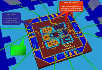
I plan to attend the conference, especially the morning session about MIPI, a Tutorials given by Texas Instruments (M-PHY), Arteris (LLI Implementation challenges) and Cadence (New MIPI protocols), but, if you’re more interested about RF Modeling and RF Design, the session run in parallel. The conference agenda can be found here, just click on the agenda:
Also, you should not miss the Keynote talk from Mike Muller, ARM CTO, “A 2020 View & Perspective”:
Comparing the original ARM design of 1985 to those of today’s latest microprocessors, Mike will look at how far has design come and what EDA has contributed to enabling these advances in systems, hardware, operating systems, and applications and how business models have evolved over 25 years. He will then speculate on the needs for scaling designs into solutions for 2020 from tiny embedded sensors through to cloud based servers which together enable the internet of things. He will look at what are the major challenges that need to be addressed to design and manufacture these systems and proposes some solutions.
Mike Muller was one of the founders of ARM. Before joining the Company, he was responsible for hardware strategy and the development of portable products at Acorn Computers and was part of the original ARM design team. He was previously at Orbis Computers who developed network computers. At ARM he was VP, Marketing from 1992 to 1996 and EVP, Business Development until October 2000 when he was appointed Chief Technology Officer. In October 2001, he was appointed to the board of ARM Holdings plc.
If you plan to attend it will be a pleasure to meet you there!
By Eric Esteve from IPnest